
Hello guys! I am Nikolas and today I’ll show you how to make an RGB Lamp that you can control with your smartphone via WiFi which is also battery powered and can be recharged using USB type C!

- STEP 1: Understand how it works
- STEP 2: 3D Designing
- STEP 3: 3D Printing
- STEP 4: Flashing the Board
- STEP 5: Setting Up Connection with the APP
- STEP 6: Quick Test
- STEP 7: Circuit Diagram
- STEP 8: Installing the Switch
- STEP 9: Soldering the Battery
- STEP 10: Soldering the TP4056 Charger
- STEP 11: Installing the Led Strip
- STEP 12: Connecting Battery to Charger
- STEP 13: TP4056 Placement
- STEP 14: Wemos D1 Mini Connections
- STEP 15: Connecting Led Strip
- STEP 16: Attaching the Led Holder
- STEP 17: Adding the Diffuser
- STEP 18: Enjoy your creation!
Before we start making you should watch the YouTube video below to check out the Lamp in action! Full instructions are included in the video as well!
Let’s first take a look at the components and tools we are going to need.
| Components | AliExpress | Banggood |
|---|---|---|
| Wemos D1 Mini Lite (V1) |  | |
| TP4056 USB Type C | | |
| Slide Switch (11mm x 6mm) | | |
| 18650 Battery | | |
| WS2812B (1m/60leds) | | |
| 100uF Capacitor | | |
| White Filament | ||
| Generic Filament (PLA, PETG, ABS etc.) | ||
| 3D Printer | | |


STEP 1: Understand how it works
Firstly think of the Wemos board as an Arduino that also happens to have WiFi. Secondly you should know that the WS2812B led strip we are using is an “ARGB/ Addressable RGB Led strip” this means that every LED is equiped with a tiny microchip and, as a result, we can control each led respectively. A lot of people here on Instructables have made amazing projects using this kind of led strip so make sure to check them out! To control the leds from our smartphone we’ll be using the firmware from a great open-source platform called “WLED“. These parts in combination with a simple switch, a rechargable battery and a charger will be fitted inside three 3D printed parts.
Now that you get how it works let’s start making it!
STEP 2: 3D Designing


I designed the parts in Fusion 360. Basically the “LampBase” is where the charger, the wemos board and the switch are. The WS2812B wraps around the “LedHolder” and secures in the two clips. Also, the cylinder is hollow and the battery fits exactly inside. There are no screws needed because I have integrated a screw and a nut in the design. Lastly the white “Diffuser” secures into the precise gap of the “LampBase”.
STEP 3: 3D Printing
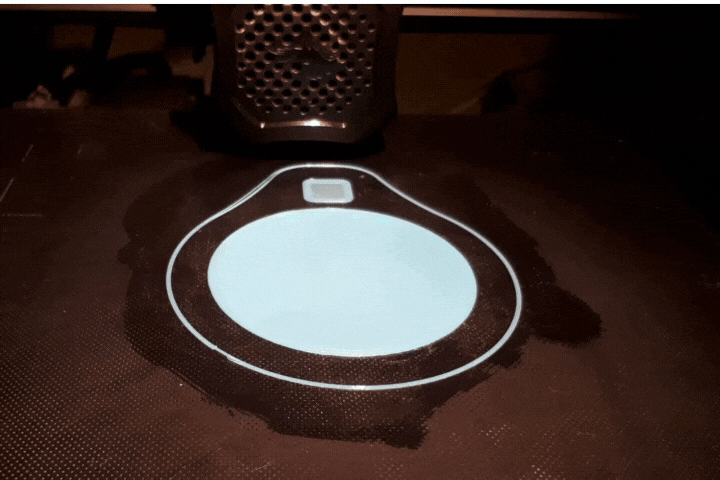
You can download all the 3D files from Here
All the parts should be printed at a 0.2mm layer height, 0.4mm walls and around 30% infill.
- The “LampBase” can be printed in any material you like. I used PLA.
- The “LedHolder” should be printed with 4 walls. I suggest using a material like PETG or ABS due to the fact that the LED strip can get hot at times. PLA will probably work well too though.
- The “Diffuser” must be printed in White with Vase/Spiralize Outer Contour mode enabled. You will also need to increase the bottom layers to 10. If you wish you can add a color change in the bottom of the part from Cura. Go to Extensions>Post Processing>Modify G-Code>Add Script then select the “Pause at height” option. Then in the top right select “Layer Number” instead of “Height” and below that write “5”. Click close and you are set to go! The printer will automatically pause when it finishes layer 5 and you’ll be able to change the color to white!
STEP 4: Flashing the Board
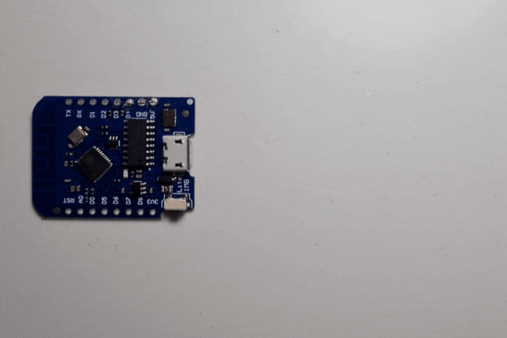
- Connect the Wemos D1 Mini to a computer using a USB cable
- Download esphome-flasher on your computer.
- Download the latest WLED Release (we are using the Lite version of the board so we’ll be downloading the “…ESP8266_1M.bin” file, if you are using a non-lite version of the board go for the “…ESP8266.bin” file.
- Open the esphome-flasher.
- Click browse and select the WLED release you downloaded earlier.
- Click Flash (The process will take around 3 minutes)
Don’t disconnect the board from your computer yet.
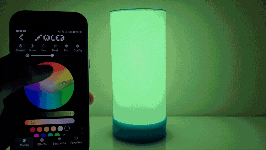
STEP 5: Setting Up Connection with the APP
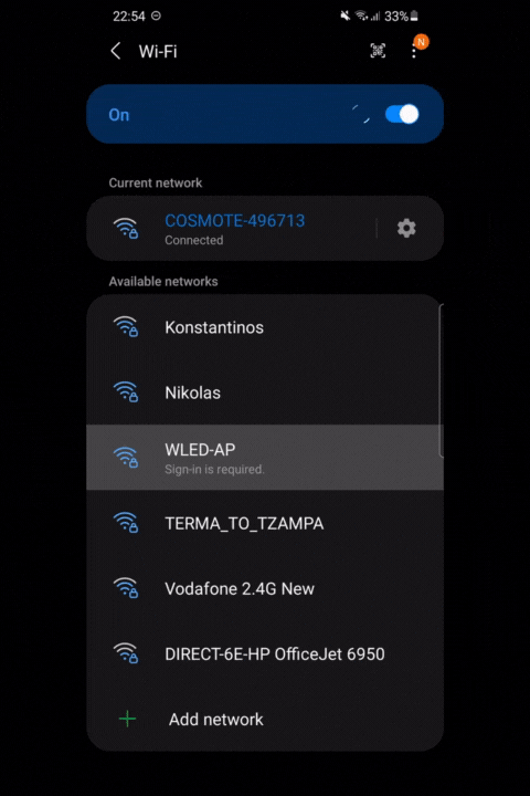
- Go over to Play/App Store and download the WLED App by Aircookie
- Go to your WiFi settings and click on a device with the name “WLED-AP“
- A page will open up and you’ll need to write your Home Network’s Name and Password
- When you finish click “Save & Connect”
- Now connect your phone to your network
- Open the WLED App
- Click the Plus (+) icon on the top right
- Select “Discover lights” and once your lights are found click the tick icon.
- Now you can click on the instance you just made and a menu with dozens of colors and effects will come up!
Troubleshooting
If the “Discover lights” function didn’t work for you, don’t worry, there is another method to connect to your RGB Lamp. Simply download Angry Ip Scanner and click “Start”. Scanning will take a few seconds, then look for a device with the name “wled-WLED“or something similar. You can see a number written next to it, that’s the IP Address. In my case it was 192.168.1.26 . Now go over to the WLED App and click on the plus icon again, and write down the IP address. It should be working now! You can also use the IP address to control the Lamp through Chrome, Safari etc,
STEP 6: Quick Test


Before soldering and assembling the lamp we need to make sure that everything is working correctly.
Connect:
- 5V to 5V
- GND to GND
- D4 to Din
Lastly, connect the battery by connecting the positive (+) to 5V and the negative (–) to GND.
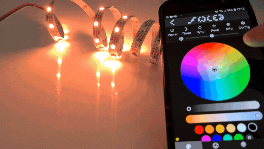
Open the app on your phone and check to see if everything is working as it should by trying different colors and effects. In our case everythings is working well but before you go soldering everything together go to Settings > Led Preferences and change the Led Count to 60 (it was probably defaulted to 30) and also adjust the Maximum Current as you like. I decided to put it at 1A=1000mA for a good balance between brightness, battery life and heat produced.
STEP 7: Circuit Diagram
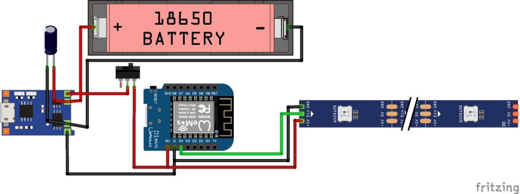
It’s finally time to start soldering and putting everything together!
STEP 8: Installing the Switch


- Solder a, preferably red, wire on the one pin of the switch.
- Solder two more red wires on the other pin.
- Push the switch into place.
STEP 9: Soldering the Battery


Soldering Li-On batteries can be really dangerous, so please be careful.
- Solder a red wire to the battery’s positive side
- Solder a black wire to the battery’s negative side
- Push the battery into place
STEP 10: Soldering the TP4056 Charger


- Connect the cathode of the Capacitor (the side with the white line) to the negative output of the TP4056 and the anode to the positive. (This capacitor is used to smooth out the output current of the charger module and it is not necessary for the circuit to work)
- Connect two black wires to the negative output of the TP4056 as well.
- Connect the single wire of the switch to the positive ouput.
STEP 11: Installing the Led Strip


Wrap the led strip around the “LedHolder”, make sure to also secure the strip into the two integrated clips of the holder.
STEP 12: Connecting Battery to Charger


- Connect the battery’s red wire to B+
- Connect the battery’s black wire to B-
STEP 13: TP4056 Placement

Simply put the charger into place
STEP 14: Wemos D1 Mini Connections

- Connect one of the two red wires of the switch to the 5V of the microcontroller.
- Connect one of the two black wires of the charger to the GND of the board.
- Connect a new wire to D4 (it’s orange in my case).
STEP 15: Connecting Led Strip


- Solder the other red wire to the strip’s 5V
- Solder the black wire to GND
- Connect Din to D4 (orange wire)
I would also advise you to insulate the joints using heat shrink tubes.
STEP 16: Attaching the Led Holder


- Place the Wemos D1 mini into the “LampBase”
- Screw the “LedHolder” into the “LampBase”
STEP 17: Adding the Diffuser


- Add the “Diffuser”
- You can charge the battery using a USB C cable. In my experience so far the battery life is more than 3 hours and charging may take up to 2 hours. (While charging the LED of the module will glow red, once the battery is full it will turn blue.)
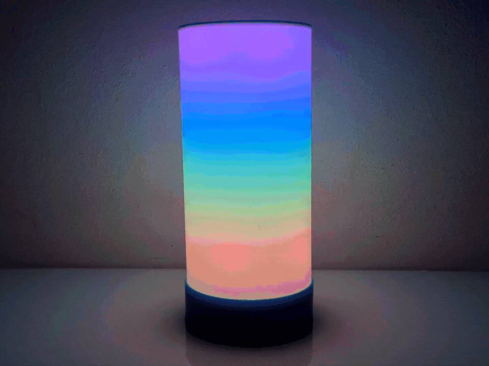
STEP 18: Enjoy your creation!

Turn on your Lamp, connect to it through the App, select your favorite effect and Enjoy!!
I hope you liked this tutorial as much as I did making it! If you have any questions or suggestions let me know! Lastly consider subscibing to my YouTube Channel for more tutorials and cool builds and to support me throughout this journey. Have a nice day!