
The Pinout diagram of all the below LCD Modules are the same
- LCD1604 – 16 char / 4 line
- LCD2004 – 20 char / 4 line
- LCD1602 – 16 char / 2 line
- LCD1601 – 16 char / 1 line etc…
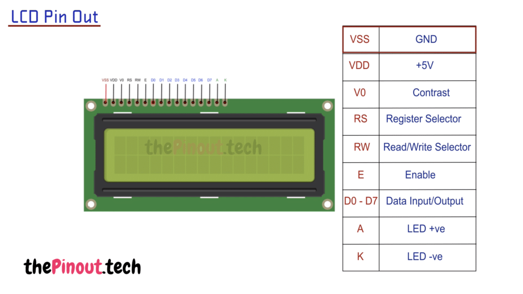
| PIN NUMBER | NAME | DESCRIPTION |
|---|---|---|
| 1 | VSS (0v) | Ground Potential |
| 2 | VDD (5v) | Positive Voltage |
| 3 | V0 (Contrast) | Contrast adjustment; 0v: Max contrast; 5v: Min contrast |
| 4 | RS | Register Select; 0: Instruction Register 1: Data Register |
| 5 | RW | Read Write Select pin 0: Write mode; 1: Read mode; |
| 6 | E | Enable Pin To enable the LCD Module |
| 7 | D0-D7 | LCD Data Bus line. They are responsible for the parallel data transfer. |
| 15 | LED+ (A) | Back Light Source LED Anode |
| 16 | LCD- (K) | Back Light Source LED Cathode |