
Introduction:
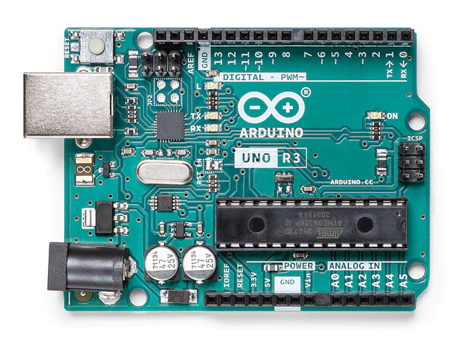
The Arduino Uno is a popular microcontroller board that has revolutionized the world of DIY electronics. Its versatility, affordability, and simplicity make it an excellent choice for beginners and experts alike. At the heart of its functionality lies the Arduino Uno pinout, which serves as a gateway to unleash a plethora of creative possibilities. In this blog post, we will explore each pin on the Arduino Uno, highlighting its capabilities and different uses.

Read more on Arduino UNO here: https://docs.arduino.cc/hardware/uno-rev3
Digital Pins (0-13):
The Arduino Uno features 14 digital input/output (I/O) pins labeled from 0 to 13. These pins can be configured as either inputs or outputs, allowing you to interface with various electronic components. They support digital signals (HIGH or LOW) and can be used for reading switches, buttons, or sensors, as well as controlling LEDs, relays, and other digital devices.
Analog Pins (A0-A5):
The Arduino Uno includes six analog input pins labeled A0 to A5. These pins can be used to measure analog voltages ranging from 0 to 5 volts. They are primarily used to interface with analog sensors such as temperature sensors, light sensors, and potentiometers. The analog input pins use a 10-bit analog-to-digital converter (ADC), providing 1024 discrete levels of resolution.
Power Pins:
- a. 5V and 3.3V: The Arduino Uno provides a regulated 5-volt output (5V) and a 3.3-volt output (3.3V). These pins can be used to power external sensors or other low-power devices that require these voltages.
- b. GND: The ground (GND) pins serve as the common reference for electrical signals. They are connected to the ground of the power supply and must be connected to complete electrical circuits.
PWM Pins:
The Arduino Uno has six pins (3, 5, 6, 9, 10, and 11) that support Pulse Width Modulation (PWM). PWM allows you to control the intensity of digital signals by rapidly switching them on and off. These pins can be used to control the brightness of LEDs, drive motors at variable speeds, and generate audio tones.
Reset Pin:
The reset pin (RESET) is used to restart the Arduino Uno. By connecting this pin to ground momentarily, you can reset the microcontroller and start your program execution from the beginning.
SPI Pins:
The Arduino Uno features dedicated pins for Serial Peripheral Interface (SPI) communication. These pins include: a. MOSI (Master Out Slave In): Used for data transmission from the Arduino to other devices. b. MISO (Master In Slave Out): Used for data transmission from other devices to the Arduino. c. SCK (Serial Clock): Provides the clock signal for synchronizing data transfer. d. SS (Slave Select): Enables communication with specific SPI devices when multiple devices are connected.
I2C Pins:
The Arduino Uno supports I2C (Inter-Integrated Circuit) communication through two pins: a. SDA (Serial Data): Carries the data signal for bi-directional communication between the Arduino and other devices. b. SCL (Serial Clock): Provides the clock signal for synchronization in I2C communication.
Interrupt Pin:
The Arduino Uno has two pins, labeled 2 and 3, that can be used as external interrupt pins. These pins can detect changes in voltage levels and trigger interrupts, allowing you to respond to external events promptly.
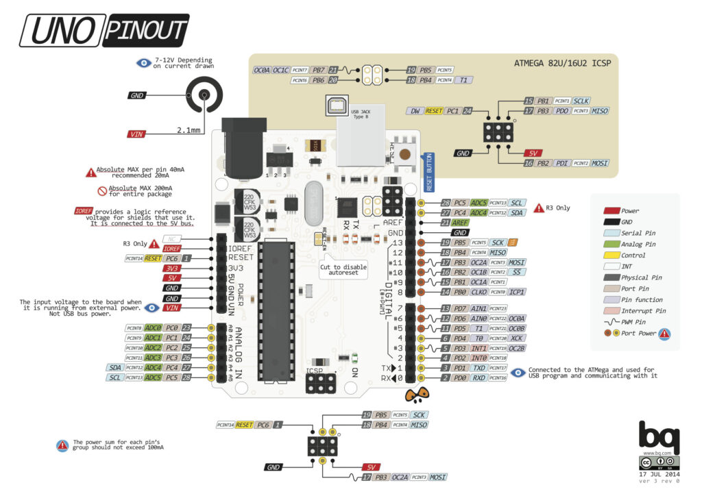
Mapping Arduino Pins to Atmega328P Pins:
To understand the correspondence between the Arduino Uno pins and the Atmega328P microcontroller pins, refer to the following table:
| Arduino Pin | Atmega328P Pin | Pin Function(s) |
|---|---|---|
| 0 | PD0 (RXD) | Digital I/O, Serial data (UART) |
| 1 | PD1 (TXD) | Digital I/O, Serial data (UART) |
| 2 | PD2 | Digital I/O, External interrupt 0 |
| 3 | PD3 (INT1) | Digital I/O, External interrupt 1 |
| 4 | PD4 (OC1B) | Digital I/O, PWM output |
| 5 | PD5 (OC1A) | Digital I/O, PWM output |
| 6 | PD6 (OC2B) | Digital I/O, PWM output |
| 7 | PD7 | Digital I/O |
| 8 | PB0 (ICP1) | Digital I/O, Timer/Counter1 input capture |
| 9 | PB1 (OC1A) | Digital I/O, PWM output |
| 10 | PB2 (OC1B) | Digital I/O, PWM output |
| 11 | PB3 (OC2A) | Digital I/O, PWM output |
| 12 | PB4 (SS) | Digital I/O, SPI Slave Select (SS) |
| 13 | PB5 (SCK) | Digital I/O, SPI Clock (SCK) |
| A0 | PC0 (ADC0) | Analog input (ADC), Digital I/O |
| A1 | PC1 (ADC1) | Analog input (ADC), Digital I/O |
| A2 | PC2 (ADC2) | Analog input (ADC), Digital I/O |
| A3 | PC3 (ADC3) | Analog input (ADC), Digital I/O |
| A4 | PC4 (SDA) | Analog input (ADC), I2C data |
| A5 | PC5 (SCL) | Analog input (ADC), I2C clock |
PD: Port D
PB: Port B
PC: Port C
ADC: Analog-to-Digital Converter
INT: Interrupt
RXD: Receiver Data (Serial communication input)
TXD: Transmitter Data (Serial communication output)
SPI: Serial Peripheral Interface OC: Output Compare (used for PWM outputs)
In the context of the Arduino Uno, these abbreviations refer to specific registers or functionalities within the Atmega328P microcontroller, which is the main microcontroller chip used on the Arduino Uno board. The ports (PD, PB, PC) refer to the different sets of pins available on the microcontroller, and the ADC, INT, RXD, TXD, SPI, and OC abbreviations are used to represent the different features and capabilities associated with those pins.
Note: The mapping of Arduino pins to Atmega328P pins provided in the table is specific to the Arduino Uno board, which utilizes the Atmega328P microcontroller. Other Arduino boards may have different pin configurations, so always refer to the appropriate documentation for accurate pin mappings.
Conclusion:
Understanding the Arduino Uno pinout is crucial for harnessing the full potential of this remarkable microcontroller board. Each pin offers unique capabilities that can be utilized in a wide range of projects. Whether you’re a beginner or an experienced maker, the Arduino Uno’s pinout provides the foundation for exploring the world of electronics and unleashing your creativity. So, grab your Arduino Uno, dive into the possibilities of each pin, and embark on an exciting journey of innovation.