
In this project, we are going to build an IR remote control relay PCB that can control up to 4 onboard relays. This PCB can be used in different applications like where you need to wirelessly switch ON/OFF devices in your home or office from the comfort of your bed or chair.

We have also used the EEPROM memory of the Atmega328 to store the state of the relays, so if the power goes off and when back on then the relays will be in the same states.

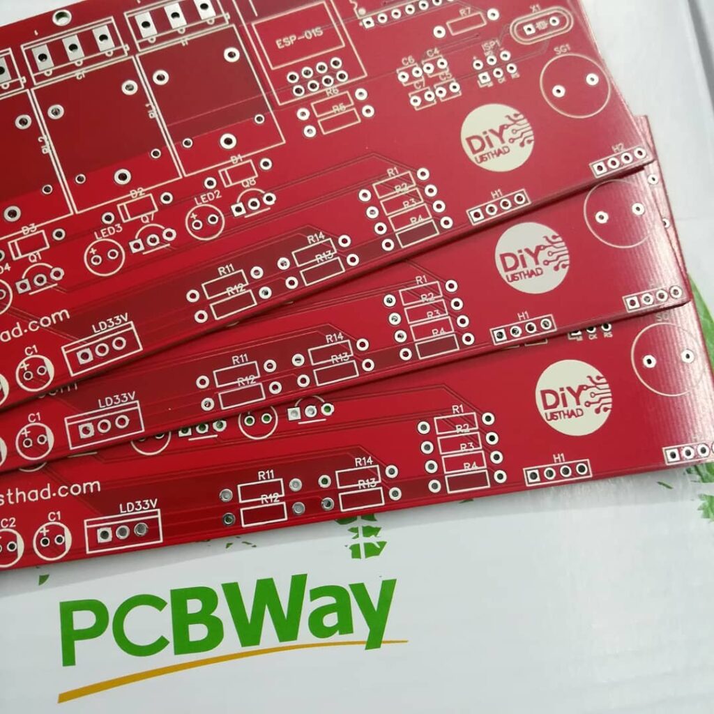
About the PCB
The PCB is having a buzzer which we can use for feedbacks like for indicating errors or when changing the state of Atmega328 pins etc… other than that 6 unused I/O pins including 1 Digital (D3) and 5 Analog pins (A0,A1,A2,A3,A5) are broken out to the edge of the PCB so that we can use them for extending the capabilities of this PCB.
This project is sponsored by ![]() . As you know PCBWay is a high-end PCB prototyping and manufacturing company, they are also providing a wide variety of other services like PCB assembly service, 3D printing, CNC machining, Sheet metal fabrication, and injection modeling.
. As you know PCBWay is a high-end PCB prototyping and manufacturing company, they are also providing a wide variety of other services like PCB assembly service, 3D printing, CNC machining, Sheet metal fabrication, and injection modeling.

For ordering the PCB of this project directly from ![]() just click here.
just click here.
Things Required
| Components | Quantity | DIY Usthad | AliExpress |
|---|---|---|---|
| IR Receiver | 1 | ||
| 12v Relay | 4 |  | |
| Atmega328p | 1 | | |
| LM7805 | 1 | ||
| BC547 | 4 | | |
| 1N4007 | 4 | | |
| Capacitor 63v 10uF | 2 | ||
| Capacitor 22pF | 2 | ||
| Resistor kit (1k ,2.2k) | |||
| 16 MHz Crystal | 1 | ||
| Header pins (male & female) | |||
| LED | 4 | ||
| Screw Terminal 1×3 | 4 | | |
| Screw Terminal 1×2 | 1 | ||
| PCB | 1 | |
Decoding the IR remote signals
Previously we have done a project for decoding the IR remote signals, you can follow that tutorial for decoding the signals of your IR remote.
We need 5 buttons from an IR remote for the below program, for turning ON/OFF the 4 onboard relays on the PCB, and one button for turning OFF all the relays. After obtaining the decimal code for each of the IR signals replace it in the below Arduino code in the place mentioned.
Code
Explanation
Initially, when the IR receiver receives a signal it will be decoded to decimal values and will be stored to the integer variable “code“. Then using if condition the received signals will be checked against the stored values. Then if the signal received is equal to the one stored the the state of the corresponding relay will be checked using another if-else statement.
If the relay is in OFF condition then the relay will be turned ON and if the relay is in ON condition it will be turned OFF, and whenever there is a change in the state of the relay then the last state will be updated to the EEPROM memory.
#include <IRremote.h>
#include <EEPROM.h>

//change the below code according to your remote
int remote_one = 29325; //relay1
int remote_two  =  -20401; //relay2
int remote_three  = 12495; //relay3
int remote_4  = 21165; //relay4
int allOff = 765; //off all relay

#define relay1 5
#define relay2 6
#define relay3 7
#define relay4 8

#define unused1 3
#define unused1 A5
#define unused1 A3
#define unused1 A2
#define unused1 A1
#define unused1 A0

#define buzzer A4

int code;

const int RECV_PIN = 2;

IRrecv irrecv(RECV_PIN);
decode_results results;

void setup()
{
  Serial.begin(9600);
  irrecv.enableIRIn();

  pinMode(relay1, OUTPUT);
  pinMode(relay2, OUTPUT);
  pinMode(relay3, OUTPUT);
  pinMode(relay4, OUTPUT);

  pinMode(buzzer, OUTPUT); digitalWrite(buzzer, LOW);

  digitalWrite(relay1, EEPROM.read(0));
  digitalWrite(relay2, EEPROM.read(1));
  digitalWrite(relay3, EEPROM.read(2));
  digitalWrite(relay4, EEPROM.read(3));

  Buzzer();
}

void loop()
{
  ir();
  code = 0;
}

void Buzzer()
{
  digitalWrite(buzzer, HIGH);
  delay(30);
  digitalWrite(buzzer, LOW);
}

void ir()
{
  if (irrecv.decode(&results))
  {
    //Serial.println(results.value, HEX);
    irrecv.resume();
    code = results.value, DEC;
    Serial.println(code);
    if (code == allOff)
      noRelay();
    else
      relay();
  }
  delay(100);
}

void noRelay()
{
  digitalWrite(relay1, LOW);
  digitalWrite(relay2, LOW);
  digitalWrite(relay3, LOW);
  digitalWrite(relay4, LOW);

  EEPROM.update(0, 0);
  EEPROM.update(1, 0);
  EEPROM.update(2, 0);
  EEPROM.update(3, 0);

}

void relay()
{
  if (code != 0)
  {

    if (code == remote_one)
    {
      Buzzer();
      if (digitalRead(relay1) == HIGH)
      {
        digitalWrite(relay1, LOW);
        Serial.println("Relay 1 OFF");
        EEPROM.update(0, 0);
      }
      else
      {
        digitalWrite(relay1, HIGH);
        Serial.println("Relay 1 ON");
        EEPROM.update(0, 1);
      }

      //delay(1000);
    }

    if (code == remote_two)
    {
      Buzzer();
      if (digitalRead(relay2) == HIGH)
      {
        digitalWrite(relay2, LOW);
        Serial.println("Relay 2 OFF");
        EEPROM.update(1, 0);
      }
      else
      {
        digitalWrite(relay2, HIGH);
        Serial.println("Relay 2 ON");
        EEPROM.update(1, 1);
      }

    }

    if (code == remote_three)
    {
      Buzzer();
      if (digitalRead(relay3) == HIGH)
      {
        digitalWrite(relay3, LOW);
        Serial.println("Relay 3 OFF");
        EEPROM.update(2, 0);
      }
      else
      {
        digitalWrite(relay3, HIGH);
        Serial.println("Relay 3 ON");
        EEPROM.update(2, 1);
      }
    }

    if (code == remote_4)
    {
      Buzzer();
      if (digitalRead(relay4) == HIGH)
      {
        digitalWrite(relay4, LOW);
        Serial.println("Relay 4 OFF");
        EEPROM.update(3, 0);
      }
      else
      {
        digitalWrite(relay4, HIGH);
        Serial.println("Relay 4 ON");
        EEPROM.update(3, 1);
      }
    }
  }
}
Uploading
For uploading the code we can either use a Arduino UNO and upload the code and then remove the Atmega328 microcontroller from the UNO board and insert it in our PCB. Or we can use an Arduino as ISP programmer and use the ISP headers on the PCB to upload the code.