Daily I used to get scolding from my wife ????because I always forgot to switch off the lights????in my bathroom so I decide to make a motion-activated light so the light will automatically get turned ON when I enter the bathroom and will get automatically turned OFF after sometime after I am out????
WellPCB PTY LTD, registered in Australia, is a daughter company of Uniwell Circuits Co., Ltd, which has two modern PCB factories and one PCB assembly factory, founded in April 2007. WellPCB is Focusing on Printed Circuit Board Fabrication and PCB Assembly Turnkey Services, to meet the requirement of High Quality, Low Cost, Fast Delivery, Easy Ordering for customers all over the world. With brand new equipment and total production area over 10,000 m2, WellPCB is capable of producing 30000 m2 feet of 2-32 layer PCBs and delivering over 10000 varieties monthly. We can produce quick turns to meet 24-hour delivery for double-sided PCBs, 48-hour for 4 to 8-layer and 120-hour for 10-layer or higher PCBs.
Project sponsored by wellpcb
Working
Mainly we are using a PIR motion sensor which will detect the motion using the temperature difference. When a motion is detected the OUT pin of the PIR sensor will become HIGH which we will connect to a BC547 transistor to drive the 12v or 5v relay. We can connect the light bulb to the C (common) and NO (normally open) of the relay.
Hardware Required
Circuit
Use the below circuit if you are using 5v relay ????????


- Connect the OUT of PIR sensor to the BASE of BC547 transistor via the 1k RESISTOR.
- Connect the GND of PIR sensor and EMITTER of BC547 to the main GND.
- Connect the COLLECTOR of BC547 to one of the COIL terminals of the RELAY.
- Connect 5v supply to PIR VCC and the other COIL terminal of the RELAY.
- Connect a Diode 1N4007 across the RELAY COIL terminal as shown in the circuit.
- Use the C & NO connections of the RELAY to connect to the light bulb
If you are using 12v relay instead use the below circuit ????????


- Connect the OUT of PIR sensor to the BASE of BC547 transistor via the 1k RESISTOR.
- Connect the GND of PIR sensor and EMITTER of BC547 to the main GND.
- Connect the COLLECTOR of BC547 to one of the COIL terminals of the RELAY.
- Connect 5v supply to PIR VCC.
- Connect the 12v supply to one of the RELAY COIL terminals.
- Connect a Diode 1N4007 across the RELAY COIL terminal as shown in the circuit.
- Use the C & NO connections of the RELAY to connect to the light bulb
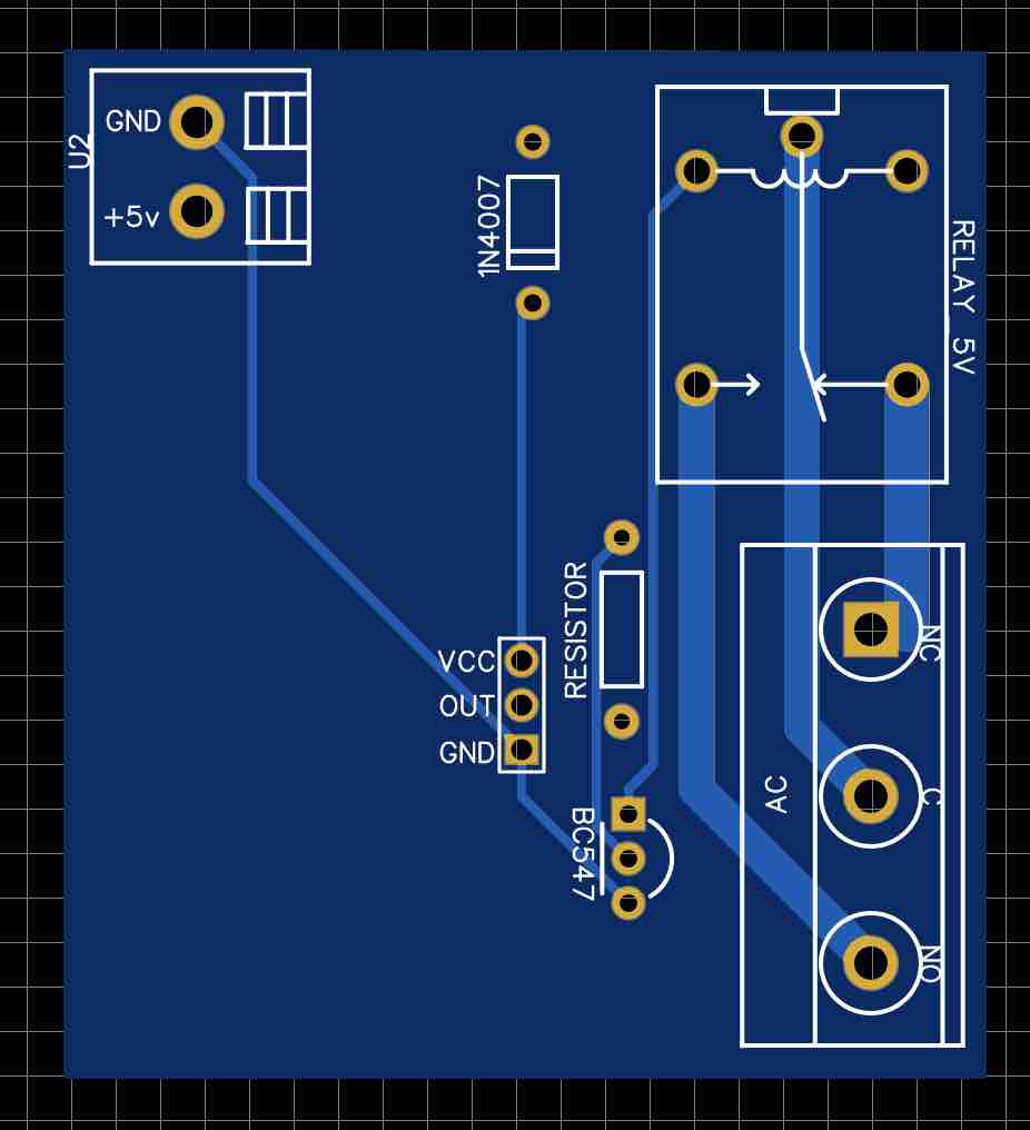
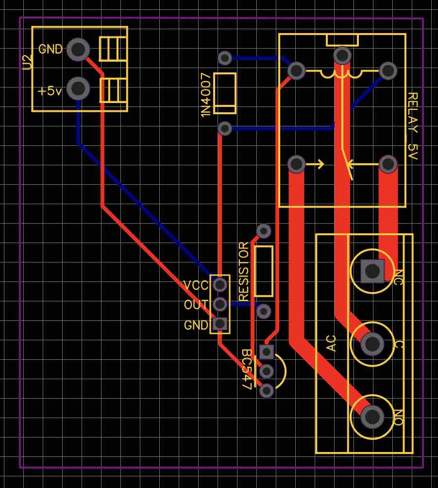
PCB
Download Gerber files
Download the PCB Gerber files for motion activated switch ????????
[wpsl_locker id=”36348″]
[/wpsl_locker]


