
Let’s learn how to use a touch switch with a single relay or relay channel to control the relays. So that we can drive high voltage appliances using touch switches.

Video
Hardware Used
| Components | DIY Usthad | Amazon.com | Banggood | AliExpress |
|---|---|---|---|---|
| TTP223 Touch Switch | ||||
| 5v Relay 2 Channel |
Pinout
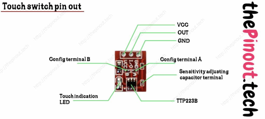
TTP223 Configurations

There are total 4 different configurations for the ttp223 touch switch for our current application we are going to use the 2nd configuration which is A is open & B is closed. By default, the ttp223 switch will be coming in configuration 1 which is both A and B are open.
Circuit

- Connect the GND of the ttp223 touch switch with the GND of the relay board.
- Connect the OUT of the ttp223 touch switch to the IN of the relay board.
- Connect the VCC of the ttp223 touch switch to the VCC of the relay board.
- Connect the negative of the 5v power supply to the common GND of the circuit.
- And finally, connect the +5v to the common VCC of the circuit as shown above in the circuit diagram.
- Now you can connect any AC appliance to the relay as shown.