
- Overview of Protective Relay
- Protective Relay Working Principle
- Protective Relay Types
- Overcurrent Relays
- Electromechanical Relays
- Directional Relays
- Distance Relays
- Protective Relay Circuit
- Protection Relay Testing
- Advantages & Disadvantages of a protection relay
- Protection Relay Applications
- Protective Relays FAQ
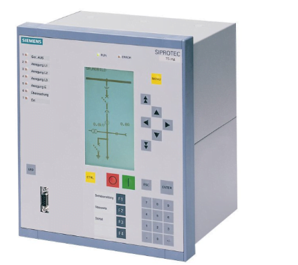
Overview of Protective Relay
The definition of a protective relay is a switch gear device used to identify problems and activate the circuit breaker to isolate the problematic component of the system. These relays are small, self-contained devices that measure electrical values continuously under fault and normal situations in order to identify abnormal conditions developing in electrical circuits. Electrical quantities including current, voltage, phase angle and frequency may alter during fault situations. Below is a diagram of the protective relay. If you want to acquire more information about the protective relays, you can look at this Electronic Part to see more electronic components.

Protective Relay Working Principle
Once a system detects a defect, a protective relay is employed to protect the equipment. Once the issue has been determined, it is located and the circuit breaker or CB is then given the tripping signal. These relays operate using electromagnetic attraction and induction theories.
The coil is attracted to the electromagnet poles by the electromagnetic attraction relay, which merely operates on both AC and DC power sources. While electromagnetic induction relays only operate on an AC source and uses an induction motor to produce torque, these types of relays operate instantly and without delay. As a result, they are frequently employed as directional relays to safeguard the electrical system as well as in applications requiring high-speed switching.
Protective Relay Types
- Overcurrent Relays
- Electromechanical Relays
- Directional Relays
- Distance Relays
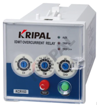
Overcurrent Relays
Overcurrent relays use the current to function. The current may be used to activate the overcurrent relays. This relay has a pick-up value, and when the measurement and amount of current exceed it, the relay turns on. These relays come in two varieties: time-delay and instantaneous, and frequently both varieties are offered in a single container. Although they are both engaged by the same current, the two pickup values can be independently changed by altering the tap settings in the input. Overcurrent relays are employed on low-voltage circuits as well as in a few particular high-voltage system applications since they are not pricey. The primary drawback of this relay is that it may potentially select current variations and faults in surrounding zones.
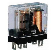
Electromechanical Relays
The early relays were electromechanical, but they are still used in many applications today. Once a control signal is sent to this relay, it simply operates by creating a magnetic field using an electromagnetic coil. This relay converts voltages and currents into electric, magnetic, and torque forces that exert pressure on the relay’s spring stresses. The two major methods by which a user sets a relay are spring strain and taps on the electromagnetic coils inside the relay. To learn more about an electromechanical relay, please click on this link.
Directional Relays
These relays are activated by the flow of current in a certain direction. It may detect a variation between the actuating & reference current. This relay is used in combination with some other relays like over current relay so that the capacity & selectivity of the protective relay system will improve. This relay simply reacts to the variation of the phase angle between both the actuating & a reference current is known as the polarizing quantity.
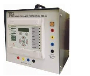
Distance Relays
This distance relay is used to distinguish between normal operating conditions & a fault and also differentiates faults within a particular area & within a different element of the system. The distance relay operation is inadequate to a particular range of impedance pickup values. This relay picks up once the impedance measurement is low or equivalent to the preferred pickup impedance value.
In this relay, the parameters like voltage & current are balanced from each other & this relay reacts to the voltage & current ratio which is the transmission line’s impedance from the location of the relay toward the point of interest. This impedance is used to determine distance through a transmission line, thus it is known as a distance relay. These relays are available in different types like reactance, mho & impedance relays.
Protective Relay Circuit
The protective relay is used to detect abnormal conditions within the electrical circuits by measuring the different electrical quantities constantly under normal as well as fault conditions. The electrical quantities which may vary in fault conditions are; current, voltage, phase angle & frequency. A typical protective relay circuit is shown which can be separated into three parts which are discussed below.
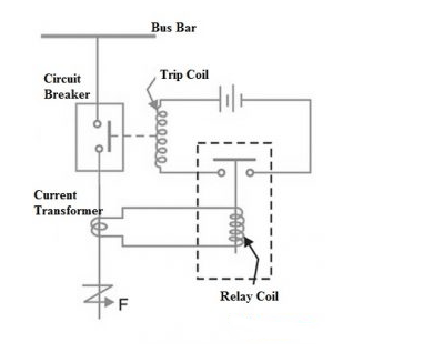
The first part of the circuit is the primary winding of a CT which is also called a current transformer. This CT is connected with the transmission line in series to be protected.
The second part includes the secondary winding of the current transformer, CB & the operating coil of the relay.
The final part of the circuit is the tripping circuit which may be either AC/DC. So it mainly includes a source of power supply, the circuit breakers trip coil & the stationary contacts of the relay.
Protection Relay Testing
Protection relays are essential components of modern power systems, thus it is essential to constantly verify for reliable performance. So testing of these relays is necessary during their lifespan. Relay testing is also necessary to ensure that proper operation is maintained on a regular basis. Electrical faults could happen and hurt personnel and damage equipment if the protection relay testing is not done properly on a regular basis.
Bench testing, commissioning testing, and maintenance testing are the three types of protective relay tests that are carried out and are covered here.
Bench Testing
This test is carried out to ensure that the relay stands alone and matches the design. This prevents more expensive and time-consuming issues from developing at later stages of a project.
Commissioning Testing
Commissioning the protective relay includes making sure the larger system functions as anticipated once the electrical system has been designed. For instance, the protective relay should function as intended and react to interlocks and other similar circumstances after it is attached to the switchgear. The relay’s functionality will have been confirmed in the future.
Maintenance Testing
The entire design intent is assumed once maintenance testing has been completed, however, the protective relay’s behavior needs to be confirmed for the following modes of operation. This relay cannot detect changes in a system’s properties, such as changing network loads over time, except for specific breakdowns. To ensure that the estimated operation is maintained in the face of these long-term changes, the protective relay may need to be reprogrammed.
Depending on the type of test, a variety of parameters, including the relay’s visual inspection, connection components, opening and closing of circuit breakers (CB), protection functions, logic functions, protective relay binary and analog input and outputs, primary injection, insulation resistance testing, and secondary injection testing, must be regularly tested.
Advantages & Disadvantages of a protection relay
- This relay monitors different parameters continuously like current, voltage, power & frequency.
- It Improves system stability through the isolation of defective section
- This relay clears the error in no time, so it reduces the damage.
- This relay detects failures & faulty sections in the system.
- It reduces the fire risk.
- It provides electrical security & protects a person while working on the system.
- It improves the performance, stability & reliability of the system.
- The operation of these relays is very fast & also very fast to reset.
- These can be utilized in both the power supplies like AC & DC.
- These relays simply work in milliseconds & the outcome is instant.
- These are the most reliable, robust, compact & very simple.
- It is applicable in different fields.
Disadvantages of a protection relay
- A protective relay cannot avoid faults within a power system, so, this relay spends more time in the power system monitoring.
- It needs periodic maintenance as well as testing not static relays.
- The operation of this relay can be simply affected because of the component’s aging, pollution & dust which results in false trips.
- These relays provide security and consistency which is required to operate with confidence.
Protection Relay Applications
- A protection relay is used in serve electrical protection.
- The protection relay detects a problem during its early stage & significantly reduces or eliminates damage to equipment.
- This relay device is mainly designed to trip a CB (circuit breaker) once a fault is noticed.
- This relay works like a detecting device, so it detects the faults, knows its position & lastly it provides the tripping signal to the circuit breaker
- This is a switchgear device used to detect the faults & begins the circuit breaker operation to separate the faulty element from the system.
- These are very helpful in high-voltage & medium-voltage protection and overcurrent to complex distance protection.