
Hello friends! My name is Nikolas and I am 15 years old. Today I’ll show you how to make a Smart Pull-Up Bar which, when you start doing Pull-Ups or Chin-Ups starts playing music in order to keep you motivated and after exercising for a certain period, a reward, a Tic Tac, in my instance gets dispensed! Make sure to watch the YouTube video below to see the Smart Pull-Up Bar in action and to follow the instructions from there if you prefer!

- Step 1: Understand How It Works
- Step 2: 3D Printing
- Step 3: Circuit:
- Step 4: Circuit Part 1
- Step 5: Circuit Part 2
- Step 6: Circuit Part 3
- Step 7: Circuit Part 4
- Step 8: Programming
- Step 9: Test/Troubleshooting
- Step 10: Circuit Board
- Step 11: Attaching the Servo
- Step 12: Pushing the Laser into the Clamp
- Step 13: Attaching the LDR to the Clamp
- STEP 14: Soldering
- Step 15: Attaching the DC Jack
- Step 16: Soldering the Switch
- Step 17: Attaching the Switch
- Step 18: Connecting Power to PCB
- Step 19: Connecting Servo to PCB
- Step 20: Connecting Speaker to PCB
- Step 21: Attaching PCB to Base
- Step 22: Cutting & Installing the Plastic Sheet
- Step 23: Installing the Laser to the Bar
- Step 24: Installing the LDR to the Bar
- Step 25: Aligning the Laser and the LDR
- Step 26: Glueing the Enclosure to the Wall
- Step 27: Connecting the Laser and the LDR to the PCB
- Step 29: Installing the Dispenser
- Step 30: Adding Cover
- Step 31: Adding Tic Tacs!
- Step 32: Congratulations the Project Is Now Complete!
Let’s first take a look at the components and tools we are going to need.
| Components | Amazon US | Amazon UK |
| Arduino Nano |  | |
| Speaker | | |
| MG90s Servo | | |
| Laser Diode | | |
| 100uF Capacitor | | |
| 5V Power Supply | | |
| DC Jack | | |
| Wires | | |
| LDR | | |
| Slide Switch | | |
| 2 x M4 Screws | | |
| 4 x M3 Screws | | |
| 5 x M2 Screws | | |
| Tic Tacs | | |
| PCB (4cm x 6cm) | | |
| Screw Terminals | | |
| Female Headers | | |
| Male Headers | | |
| Plastic Sheet | | |
| 3D Printer | | |
| Soldering Iron | | |
| Pull – Up Bar | | |
Step 1: Understand How It Works
Basically I’ve made a Laser beam sensor by attaching a cheap Laser Diode and an LDR on the Pull-Up Bar. They are perfectly aligned which means that a lot of light reaches the LDR and thus the sensor outputs a high analog value. However once I place my hands on the bar to start working out I block the light beam, the value gets significantly lower and the sensor sends a signal to the Arduino Nano, which is mounted on the wall in an enclosure and then a song starts playing using a small speaker (In my case it was Take on me by A-ha). After around 30 seconds, when the song ends, if I still have my hands on the bar, a reward, a Tic Tac gets dispensed using a 3D printed mechanism that’s rotated by a servo!
Now that you get how it works let’s start making it!
Step 2: 3D Printing
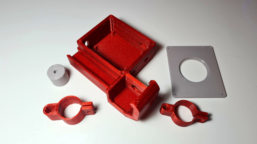
I designed all the parts in Fusion 360, sliced them in Cura and printed them with my Ender 3 V2 in PETG at 0.2mm layer height. You will need to print:
- The “Base.stl“
- The “RotatorDispenser.stl“
- The “CoverBase.stl“
- The “LaserClamp.stl“
- And the “LdrClamp.stl“
You can find all the files Here
Step 3: Circuit:
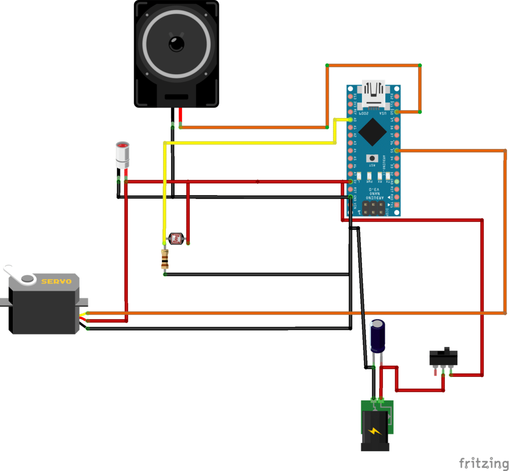
Time to put the circuit together!
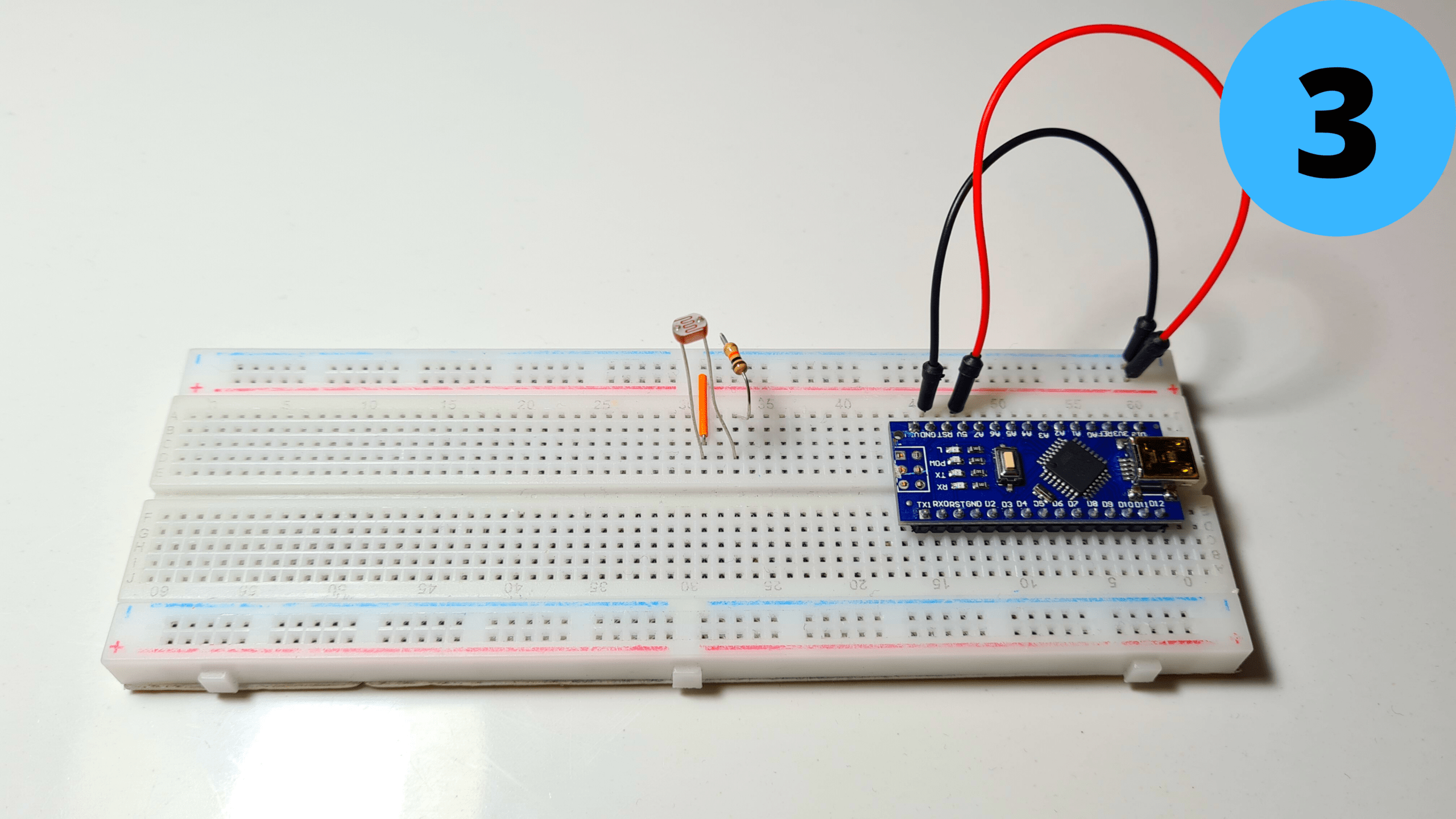
Step 4: Circuit Part 1
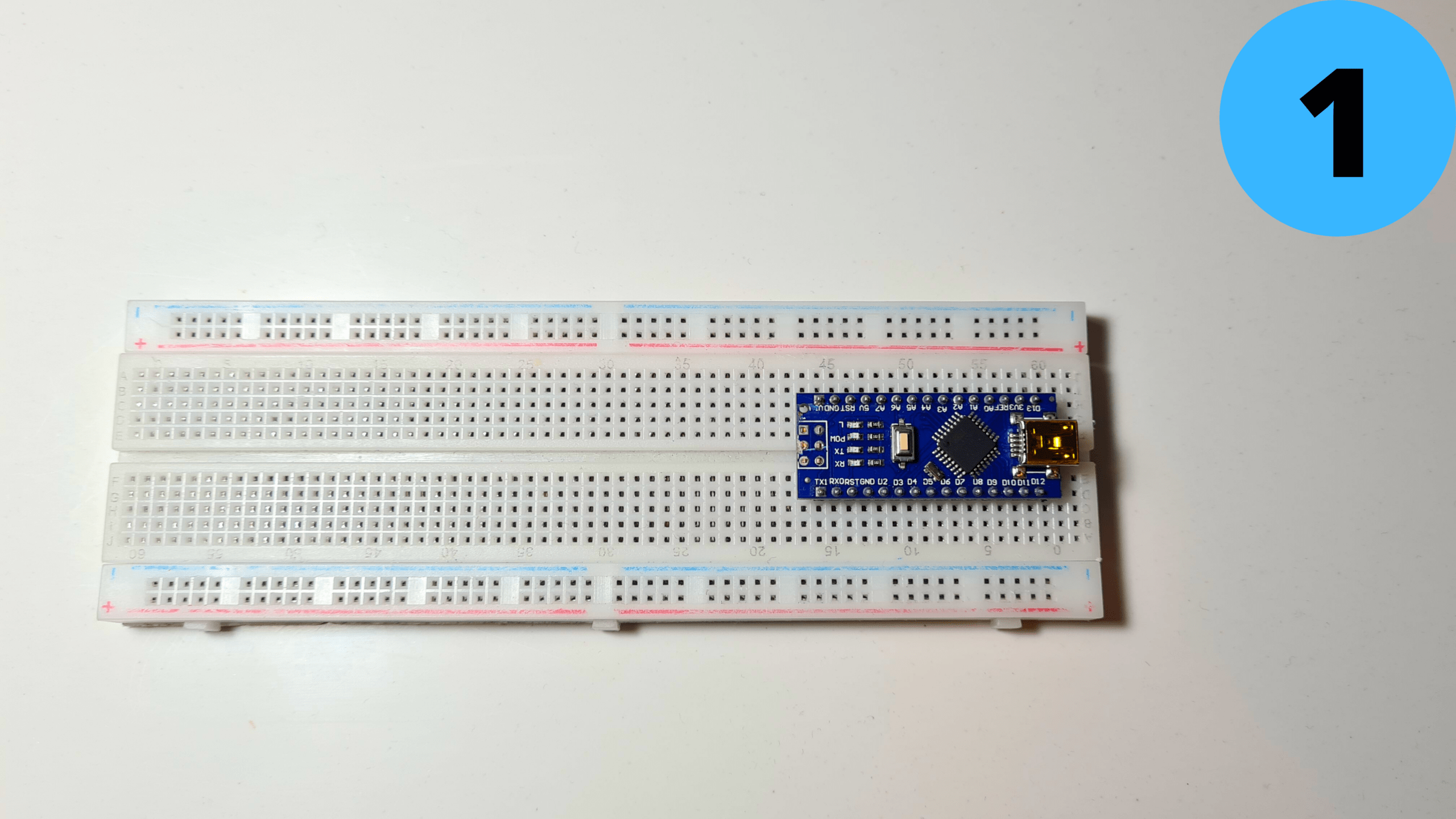
1. Place the Arduino Nano on the breadboard
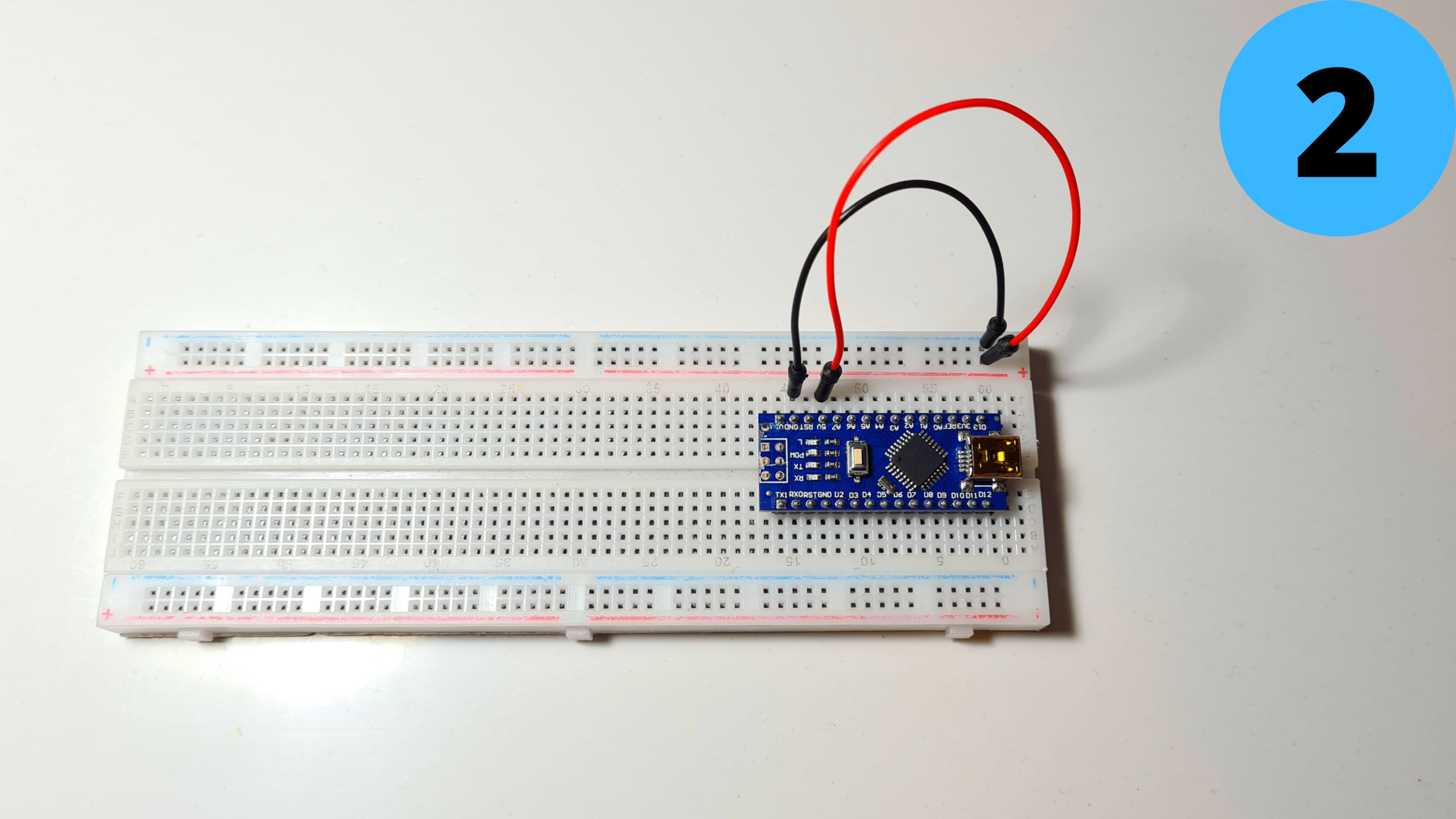
2. Connect 5V to Positive Rail (red) and GND to Negative Rail (blue)
Step 5: Circuit Part 2
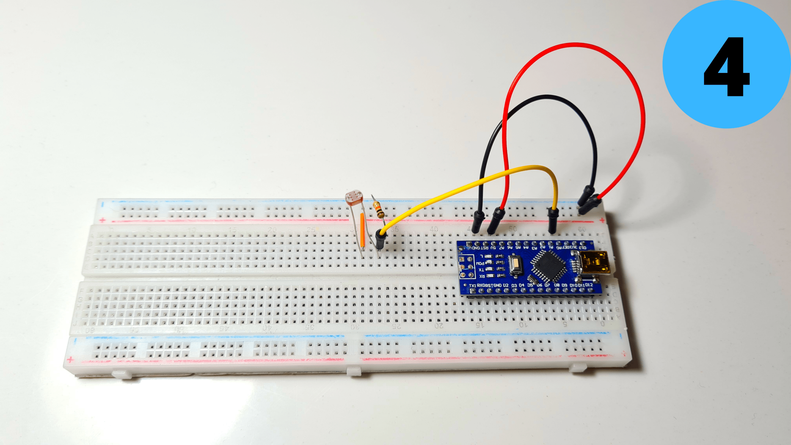
3. Add the LDR and connect one of its leads to 5V and the other one to GND with the 1kΩ resistor (the order doesn’t matter)
4.Connect the second lead to A0 as well
Step 6: Circuit Part 3
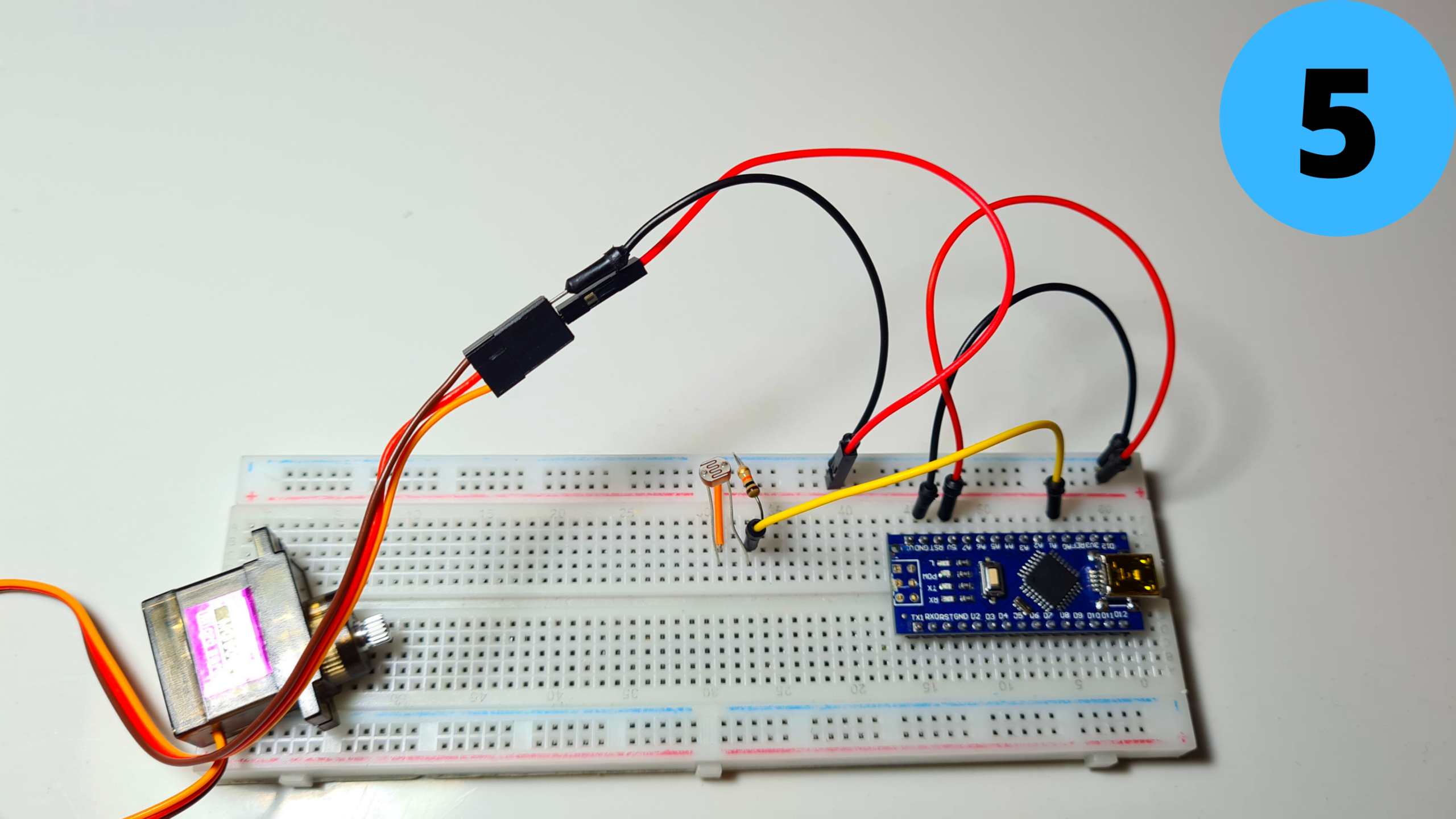
5.Add the MG90S Servo and connect its Brown Wire to GND and its Red Wire to 5V
6. Connect the YellowWire to D5
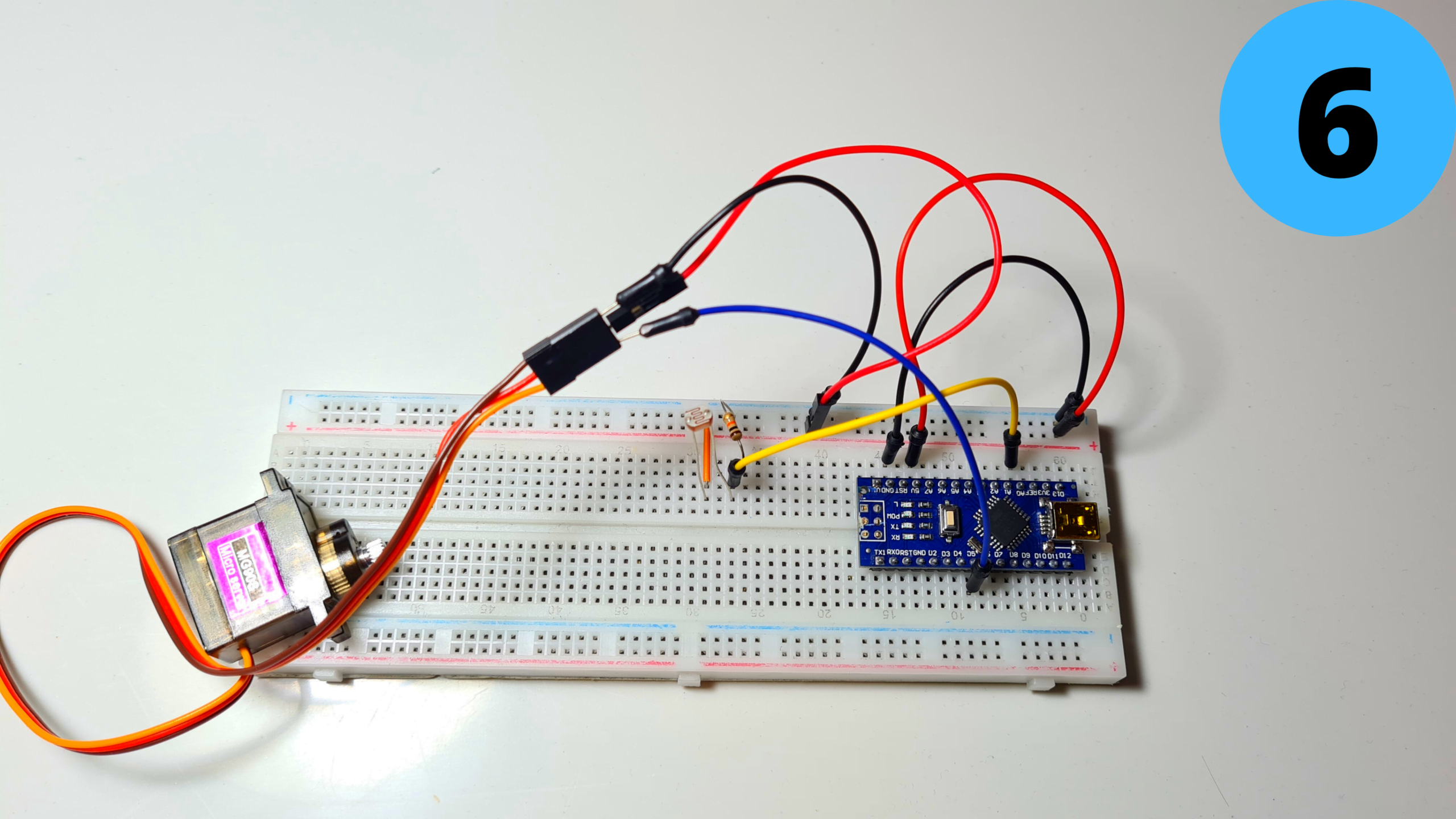
Step 7: Circuit Part 4
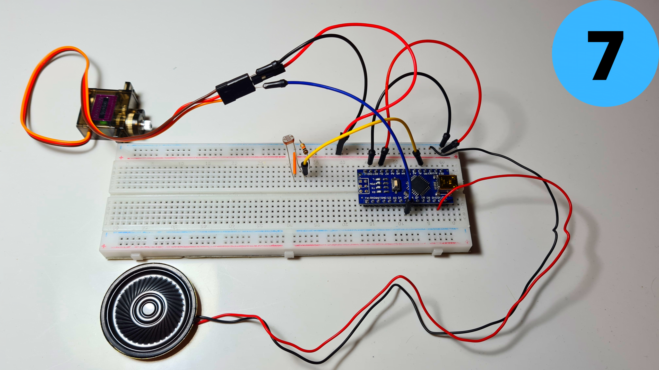
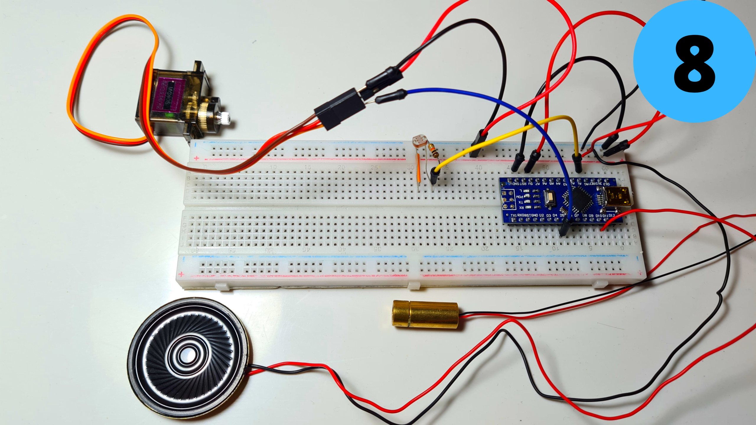
7. Add the small speaker and connect its Red Wire (+) to D11 and its Black Wire (-) to GND
8. Finally add the Laser Module and connect its Red Wire (+) to 5V and its Black Wire (-) to GND
Step 8: Programming
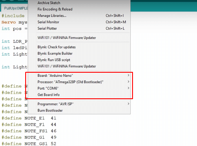
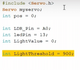
Time to program the Arduino Nano! I have attached my code below for you to download if you want. Open Arduino IDE select the Arduino Nano Board, your COM Port, click Upload and you’re done! The LightThreshold defines how sensitive the LDR is to light, keep this in mind as I’ll go into it deeper in the next step.
Take a look at adithyalokesh17‘s work as well! He has turned a lot of popular songs (Like “Take on me” which I used) into light Arduino code which is easy to use with buzzers and speakers without needing any complicated SD card readers etc.
The code:
//Nikolaos Babetas

#include <Servo.h>
Servo myservo;
int pos = 180;

int LDR_Pin = A0;
int ledPin = 13;
int LightValue = 0;

int LightThreshold = 900;


#define NOTE_B0  31
#define NOTE_C1  33
#define NOTE_CS1 35
#define NOTE_D1  37
#define NOTE_DS1 39
#define NOTE_E1  41
#define NOTE_F1  44
#define NOTE_FS1 46
#define NOTE_G1  49
#define NOTE_GS1 52
#define NOTE_A1  55
#define NOTE_AS1 58
#define NOTE_B1  62
#define NOTE_C2  65
#define NOTE_CS2 69
#define NOTE_D2  73
#define NOTE_DS2 78
#define NOTE_E2  82
#define NOTE_F2  87
#define NOTE_FS2 93
#define NOTE_G2  98
#define NOTE_GS2 104
#define NOTE_A2  110
#define NOTE_AS2 117
#define NOTE_B2  123
#define NOTE_C3  131
#define NOTE_CS3 139
#define NOTE_D3  147
#define NOTE_DS3 156
#define NOTE_E3  165
#define NOTE_F3  175
#define NOTE_FS3 185
#define NOTE_G3  196
#define NOTE_GS3 208
#define NOTE_A3  220
#define NOTE_AS3 233
#define NOTE_B3  247
#define NOTE_C4  262
#define NOTE_CS4 277
#define NOTE_D4  294
#define NOTE_DS4 311
#define NOTE_E4  330
#define NOTE_F4  349
#define NOTE_FS4 370
#define NOTE_G4  392
#define NOTE_GS4 415
#define NOTE_A4  440
#define NOTE_AS4 466
#define NOTE_B4  494
#define NOTE_C5  523
#define NOTE_CS5 554
#define NOTE_D5  587
#define NOTE_DS5 622
#define NOTE_E5  659
#define NOTE_F5  698
#define NOTE_FS5 740
#define NOTE_G5  784
#define NOTE_GS5 831
#define NOTE_A5  880
#define NOTE_AS5 932
#define NOTE_B5  988
#define NOTE_C6  1047
#define NOTE_CS6 1109
#define NOTE_D6  1175
#define NOTE_DS6 1245
#define NOTE_E6  1319
#define NOTE_F6  1397
#define NOTE_FS6 1480
#define NOTE_G6  1568
#define NOTE_GS6 1661
#define NOTE_A6  1760
#define NOTE_AS6 1865
#define NOTE_B6  1976
#define NOTE_C7  2093
#define NOTE_CS7 2217
#define NOTE_D7  2349
#define NOTE_DS7 2489
#define NOTE_E7  2637
#define NOTE_F7  2794
#define NOTE_FS7 2960
#define NOTE_G7  3136
#define NOTE_GS7 3322
#define NOTE_A7  3520
#define NOTE_AS7 3729
#define NOTE_B7  3951
#define NOTE_C8  4186
#define NOTE_CS8 4435
#define NOTE_D8  4699
#define NOTE_DS8 4978
#define REST      0

int tempo = 140;
int buzzer = 11;
int melody[] = {

  // Take on me, by A-ha
  // Score available at https://musescore.com/user/190926/scores/181370
  // Arranged by Edward Truong

  NOTE_FS5, 8, NOTE_FS5, 8, NOTE_D5, 8, NOTE_B4, 8, REST, 8, NOTE_B4, 8, REST, 8, NOTE_E5, 8,
  REST, 8, NOTE_E5, 8, REST, 8, NOTE_E5, 8, NOTE_GS5, 8, NOTE_GS5, 8, NOTE_A5, 8, NOTE_B5, 8,
  NOTE_A5, 8, NOTE_A5, 8, NOTE_A5, 8, NOTE_E5, 8, REST, 8, NOTE_D5, 8, REST, 8, NOTE_FS5, 8,
  REST, 8, NOTE_FS5, 8, REST, 8, NOTE_FS5, 8, NOTE_E5, 8, NOTE_E5, 8, NOTE_FS5, 8, NOTE_E5, 8,
  NOTE_FS5, 8, NOTE_FS5, 8, NOTE_D5, 8, NOTE_B4, 8, REST, 8, NOTE_B4, 8, REST, 8, NOTE_E5, 8,
  REST, 8, NOTE_E5, 8, REST, 8, NOTE_E5, 8, NOTE_GS5, 8, NOTE_GS5, 8, NOTE_A5, 8, NOTE_B5, 8,

  NOTE_A5, 8, NOTE_A5, 8, NOTE_A5, 8, NOTE_E5, 8, REST, 8, NOTE_D5, 8, REST, 8, NOTE_FS5, 8,
  REST, 8, NOTE_FS5, 8, REST, 8, NOTE_FS5, 8, NOTE_E5, 8, NOTE_E5, 8, NOTE_FS5, 8, NOTE_E5, 8,

};

int notes = sizeof(melody) / sizeof(melody[0]) / 2;
int wholenote = (60000 * 4) / tempo;
int divider = 0, noteDuration = 0;

void setup() {
  // put your setup code here, to run once:

  Serial.begin(9600);
  myservo.attach(5);
  myservo.write(pos);

  //myservo.detach();
}

void loop() {
  // put your main code here, to run repeatedly:


  LightValue = analogRead(LDR_Pin);
  Serial.println(LightValue);

  if ( LightValue <  LightThreshold)
  {
    for (int thisNote = 0; thisNote < notes * 2; thisNote = thisNote + 2) {

      // calculates the duration of each note
      divider = melody[thisNote + 1];
      if (divider > 0) {
        // regular note, just proceed
        noteDuration = (wholenote) / divider;
      } else if (divider < 0) {
        // dotted notes are represented with negative durations!!
        noteDuration = (wholenote) / abs(divider);
        noteDuration *= 1.5; // increases the duration in half for dotted notes
      }

      // we only play the note for 90% of the duration, leaving 10% as a pause
      tone(buzzer, melody[thisNote], noteDuration * 0.9);

      // Wait for the specief duration before playing the next note.
      delay(noteDuration);

      // stop the waveform generation before the next note.
      noTone(buzzer);


    }
    LightValue = analogRead(LDR_Pin);
    if ( LightValue < LightThreshold)
    {
      //myservo.attach(5);

      for (pos = 180; pos >= 0; pos -= 1) { // goes from 180 degrees to 0 degrees
        myservo.write(pos);              // tell servo to go to position in variable 'pos'
        delay(15);                       // waits 15ms for the servo to reach the position
      }

      delay(500);

      for (pos = 0; pos <= 180; pos += 1) { // goes from 0 degrees to 180 degrees
        // in steps of 1 degree
        myservo.write(pos);              // tell servo to go to position in variable 'pos'
        delay(15);                       // waits 15ms for the servo to reach the position
      }
    }
    delay(300000);
    // waits 15ms for the servo to reach the position
  }
}
Step 9: Test/Troubleshooting
When the code gets uploaded nothing happens. Then I cover the LDR with my finger so that I block the light from reaching it. Pretty much a simulation of what will happen during the workout when my hands will block the laser beam. In both cases the If statement gets triggered, music starts playing and then the servo rotates and dispenses a Tic Tac.
There are two common problems that can ocure here even if you did everything properly.
- The music doesn’t start playing when you cover the sensor. You can easily solve this by increasing the “LightThreshold” value we talked in the previous step thus making it more sensitive.
- The music starts playing without even covering the sensor. You can solve this be decreasing the “LightThreshold” value thus making it less sensitive.
Tips:
- A good tip to adjust the Threshold value just right would be to use the serial monitor and see the light values your sensor produces. (The can range anywhere between 0 (Absolute Darkness) to 1023 (Absolute Light)
- To get accurate measurements I would suggest aiming the laser diode to the LDR and working with those values instead of the ones of the ambient light of your room.
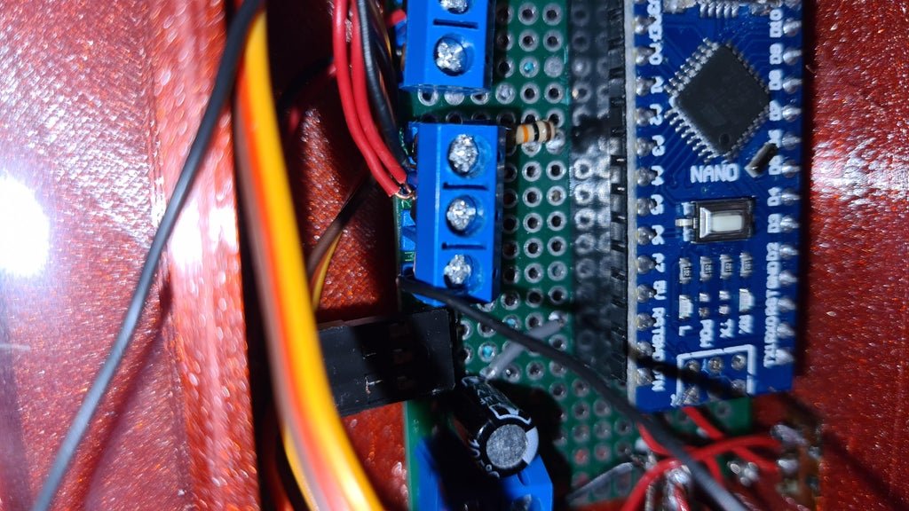
Step 10: Circuit Board
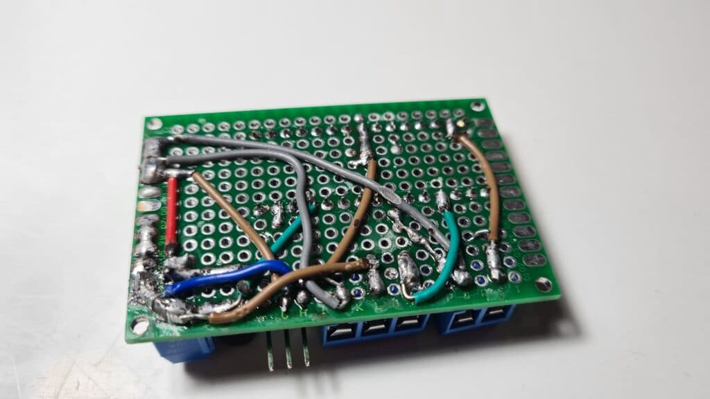
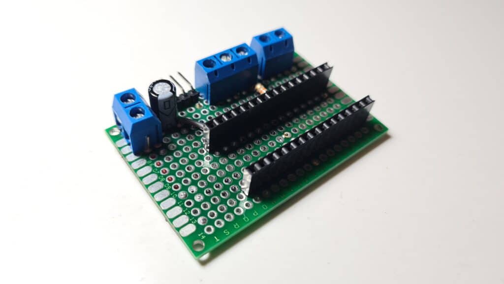
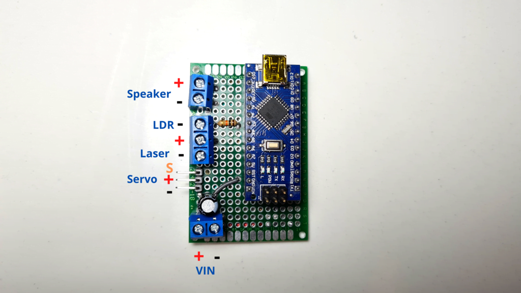
Since everything works it’s time to make a pcb to fit all the components in a more compact enclosure. The only difference the PCB has from the breadboard circuit we made earlier is that I’ve included a Power Input terminal which connects (+) to 5V and (-) to GND and I have added a 100μF capacitor (optional) in parallel to smooth out the current.
Step 11: Attaching the Servo
Screw the servo to the Base using 1 or 2 M2 screws.
Step 12: Pushing the Laser into the Clamp
Push the Laser Diode into the LaserClamp.
Step 13: Attaching the LDR to the Clamp
Insert the LDR into the LdrClamp. (There are two small holes To pass the wires through)
(You should first solder some longer wires to both the LDR and the Laser)
STEP 14: Soldering
- Solder a preferably red wire to the positive lead of the DC Jack.
- Solder a black wire to the negative lead of the DC Jack.
- Solder a new red wire to the slide switch.
Step 15: Attaching the DC Jack
Insert the DC Jack into its hole in the base. Secure it in place using the nut.
Step 16: Soldering the Switch
Solder the red wire of the DC Jack to the other lead of the switch.
Step 17: Attaching the Switch
Push the switch into place.
Step 18: Connecting Power to PCB
- Connect the red wire to the positive power input of the pcb.
- And the black wire to the negative power input.
Step 19: Connecting Servo to PCB
Connect the servo to the male headers.
Step 20: Connecting Speaker to PCB
Connect the speaker
Step 21: Attaching PCB to Base
- Fit the PCB into the Base
- Secure it in place with 2-4 M2 screws
Step 22: Cutting & Installing the Plastic Sheet
Cut the transparent plastic sheet into a rectangle of around 75mm x 17mm and trim its sides until it fits tightly into the base.
Step 23: Installing the Laser to the Bar
Attach the LaserClamp to one side of the Pull-Up Bar and tighten the clamp using an M4 screw and nut
Step 24: Installing the LDR to the Bar
Attach the LdrClamp to the other side of the Bar and tighten it again using an M4 screw and nut
Step 25: Aligning the Laser and the LDR
- Turn on the Laser Module by connecting it to a ~5V power source (Arduino 5V pin, 3 x AA batteries, 1S Lipo, 18650 battery or whatever you prefer)
- Rotate the Clamps until the Laser Beam hits the center of the LDR
Step 26: Glueing the Enclosure to the Wall
Take the Hot Glue Gun, possibly all of the makers’ most favorite tool, and glue the Base to your wall.
Step 27: Connecting the Laser and the LDR to the PCB
- Wrap the cables of the Laser and the LDR around your door
- Connect the two red wires to the central section of the triple screw terminal
- Connect the black wire of the LDR to the upper section
- And the black wire of the Laser to the other section
(Of course all these connections will differ based on how and if you make the PCB and mine can just be used as a concept reference)
Step 29: Installing the Dispenser
- Connect the Power Supply to the DC Jack and turn the switch on
When the Arduino first gets powered on, the servo automatically goes to its 0 degree position and locks in place. When that happens, attach the RotatorDispenser to it. Make sure that the two holes for the Tic Tacs align properly.
Step 30: Adding Cover
- Fit the speaker into the Cover
- Screw the cover to the Base using 2 – 4 x M3 screws
Step 31: Adding Tic Tacs!
Lastly add some Tic Tacs…
Step 32: Congratulations the Project Is Now Complete!
And the Smart Pull-Up Bar is finally complete!!
I hope you enjoyed this Instructable as much as I did making it! If you have any questions or suggestions let me know! Also consider subscribing to my YouTube Channel for more tutorials and cool builds and to support me throughout this journey. Have a great day!