In the third lesson, we are going to learn to interface a momentary push button with Raspberry Pi and program to display some output on the screen when the push button is pressed.

Hardware Required
| Components | Amazon | AliExpress | Banggoode |
|---|---|---|---|
| Raspberry Pi 3b+ | |||
| Micro Push Button |
Circuit
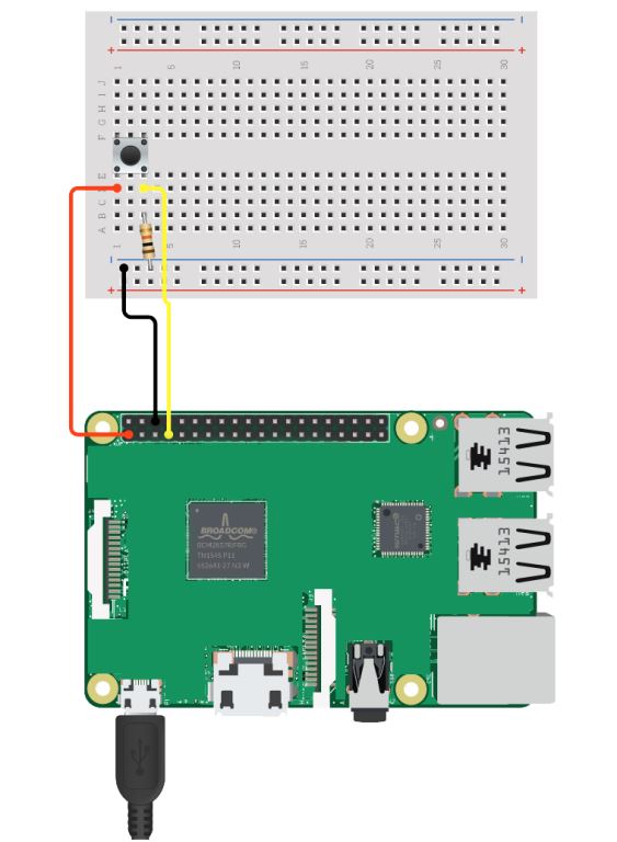
- Connect the 3.3v of Raspberry Pi to one of the terminal of Push Button.
- Connect the GPIO 4 (Physical pin 7) of Raspberry Pi to the other terminal of Push Button.
- Connect a pull down resistor from GPIO 4 to GND.
Code
// https://diyusthad.com
// https://youtube.com/diyusthad
import processing.io.*;
// On the Raspberry Pi GPIO 4 is physical pin 7 on the header
void setup() {
GPIO.pinMode(4, GPIO.INPUT);
background(0);
}
void draw() {
if (GPIO.digitalRead(4) == GPIO.HIGH) {
// button is pressed
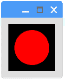
fill(255,0,0); // color changes to RED
} else {
// button is not pressed
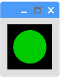
fill(0,204,0); // color changes to Green
}
ellipse(width/2, height/2, width*0.75, height*0.75); // to draw a circle
}
Output