
Introduction
In this DIY We are using MI band 2 or You can use MI band 3 to switch ON/OFF devices like fan, light or anything which comes into your mind, from anywhere in the World.

Hardware Required
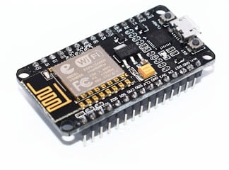 | Node MCU | x | 1 |  |
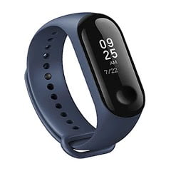 | MI band 2 or Mi band 3 | x | 1 | |
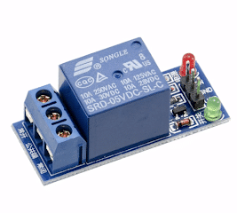 | Single Relay board | x | 1 | |
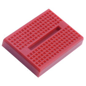 | Bread Board | x | 1 | |
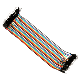 | Jumper cables | x | as required | |
Software Required
| Components | Amazon.in | Amazon.com | Banggood | AliExpress | Utsource |
|---|---|---|---|---|---|
| Node MCU | |||||
| Jumper cables | |||||
| Bread Board | |||||
| Single Relay board | |||||
| MI band 2 or Mi band 3 |
 | Arduino IDE | |
 | Mi Band 2/3 & Amazfit Сhannel ( Weather ) | |
 | IFTTT | |
 | Blynk – IoT for Arduino, ESP8266/32, Raspberry Pi |
Making
Let’s divide the process into small sections for easy understanding.
Step 1: Blynk
- Download the Blynk app from google play store
- Sign in using a valid E-mail address
- Create a new project
- Give a project name and choose NodeMCU from choose device dropdown list.
- Then choose Wi-Fi from connection type dropdown list and press Create.
- An Auth Token will be generated and send to the E-mail address which you signed in.
- Copy and save the Auth Token somewhere safe, We will use it in the next step DO NOT share it, anyone who is having it can control your device.
- Now click on the “+“
- Click on the Button widget from the dashboard to edit the button settings.
- Now from the settings choose the pin which you want to control, I’m choosing digital pin D5
- Change the ON state to 0 and OFF state to 1, by default ON will be 1 ie HIGH and OFF will be 0 ie LOW. We are doing this because Our relay will turn ON on LOW and turn OFF on HIGH.
- Change the mode to switch instead of push.
Step 2: NodeMCU
We are going to program NodeMCU with Arduino IDE.
- First, We need to install the NodeMCU support in Arduino IDE, Watch the below video on how to do it or read the instructions here,
- Secondly, We need to install the required library to run Blynk in NodeMCU,
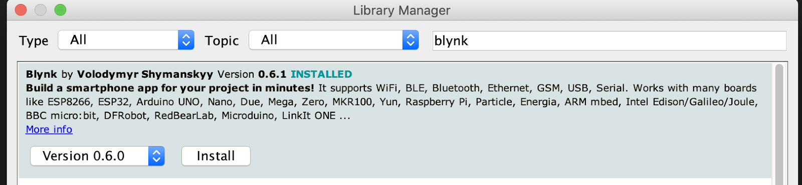 |
- Search for blynk in Library Manager and install the latest version or You can download Zip file from Github (https://github.com/blynkkk/blynk-library) and install manually using add.ZIP Library option in Arduino IDE.
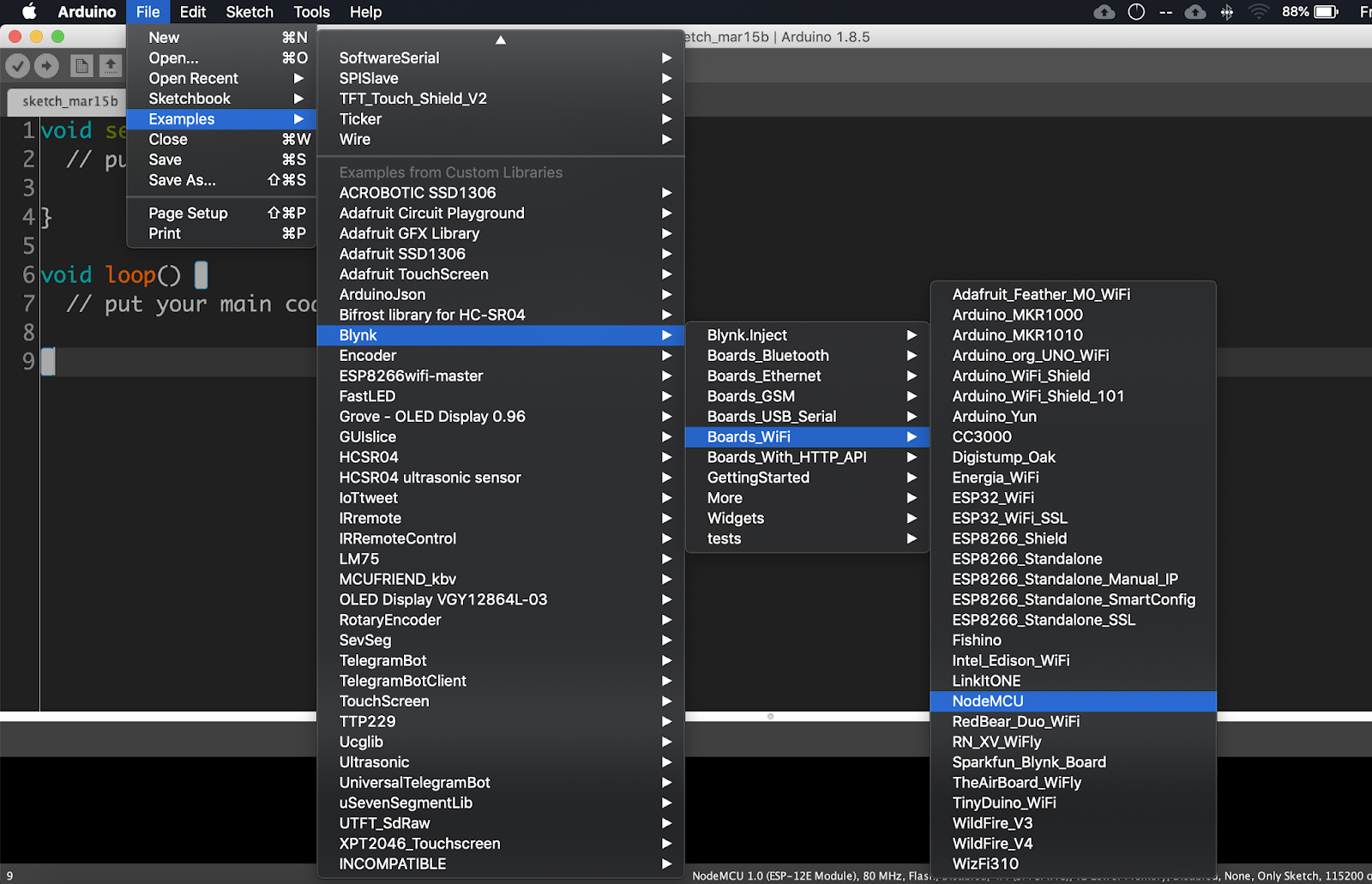
- Then, go to File -> Examples -> Blynk -> Boards_WiFi -> NodeMCU, as shown below.
- Then paste the AuthToken generated from Blynk app to the Blynk Arduino sketch.
- Type your WiFi SSID and Password also to the Blynk Arduino sketch, where it is mentioned.

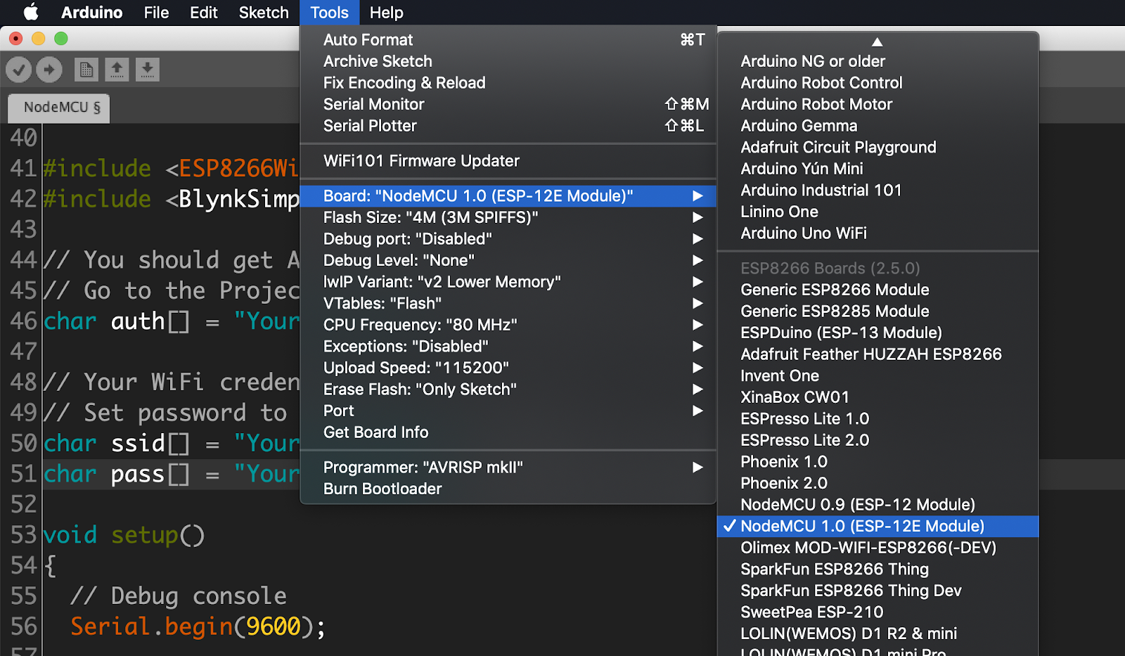
- Now select the board from the tools menu and upload the sketch.
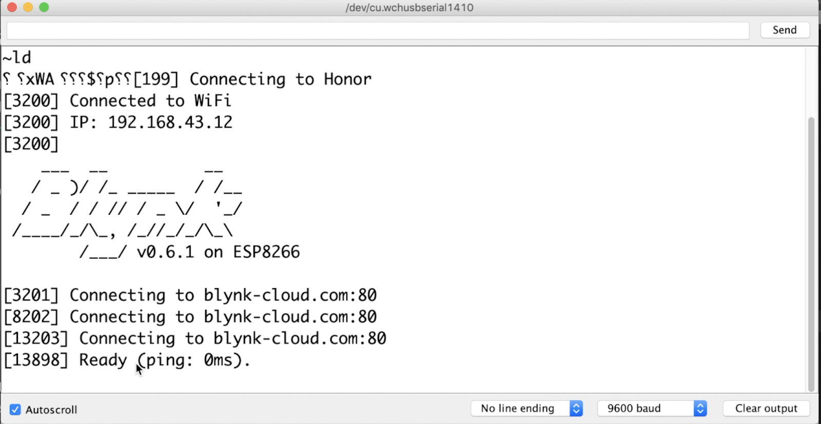
- Now open serial monitor from the tools menu, if everything is done successfully, You can see the results like this
Step 3: Relay Connection
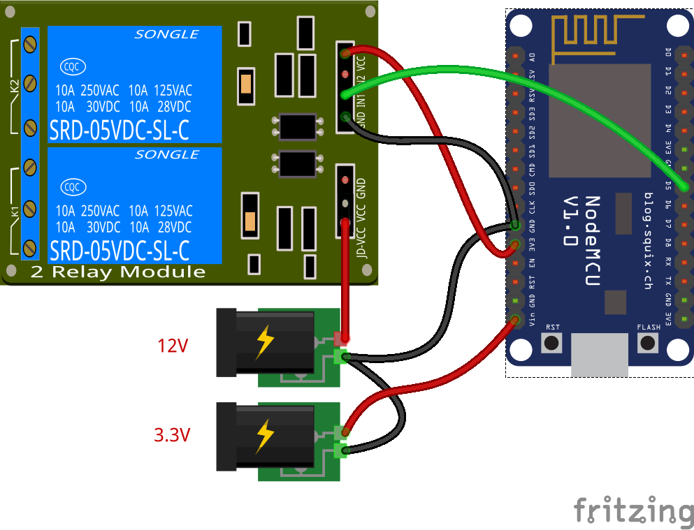
Now connect a relay to the NodeMCU so We can control external AC / DC appliances.
%22%20transform%3D%22matrix(6.25%200%200%206.25%203.1%203.1)%22%20fill-opacity%3D%22.5%22%3E%3Cellipse%20fill%3D%22%23a7a5a7%22%20rx%3D%221%22%20ry%3D%221%22%20transform%3D%22matrix(26.16511%20118.02318%20-51.72278%2011.46666%20240.8%205.1)%22%2F%3E%3Cellipse%20fill%3D%22%234c4b49%22%20rx%3D%221%22%20ry%3D%221%22%20transform%3D%22rotate(-150.2%2092.8%2038)%20scale(114.69807%2050.56079)%22%2F%3E%3Cellipse%20fill%3D%22%2392918f%22%20cx%3D%2224%22%20cy%3D%22147%22%20rx%3D%2278%22%20ry%3D%2234%22%2F%3E%3Cellipse%20fill%3D%22%2392918f%22%20cx%3D%2238%22%20cy%3D%2214%22%20rx%3D%2249%22%20ry%3D%2249%22%2F%3E%3C%2Fg%3E%3C%2Fsvg%3E)
| Power Supply | NodeMCU | Relay Channel |
| – | D5 | IN |
| 3V | VIN | VCC |
| 12V | – | VJ-VCC |
| GND | GND | GND |
Step 4: IFTTT
Either you can use IFTTT website to IFTTT mobile app to create Applets. Here I’m using IFTTT website, in the video, I have shown how to do it in the IFTTT mobile app.
Before start create IFTTT applet we need to create two HTTP request links, one for turning ON the relay and one for turning OFF the relay.
|
http://188.166.206.43/blynkAuthToken/update/D14?value=0
http://188.166.206.43/blynkAuthToken/update/D14?value=1
|
Here,
- The 188.166.206.43 is the IP address of blynk server.
- You need to replace your blynk Auth Token, where it is mentioned in the request link.
- D14 is the pin which we have connected our relay, actually, we have connected relay to the D5 pin of NodeMCU but here in the HTTP request link we need to address the GPIO pin number, so the GPIO pin number for physical pin D5 is D14.
- When we call value=0 it will make the pin D5 LOW, the relay is ON.
- When we call value=1 it will make the pin D5 HIGH, the relay is OFF
Creating Applet For Relay ON

- Go to www.ifttt.com then login using your account or signup if you don’t have an account.
- Then under applets tab click on new applets button.
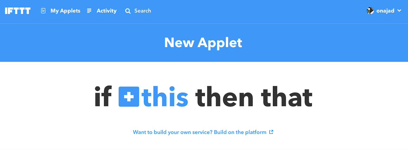
- Now, click on the +this button.
- Then choose a service page will open.
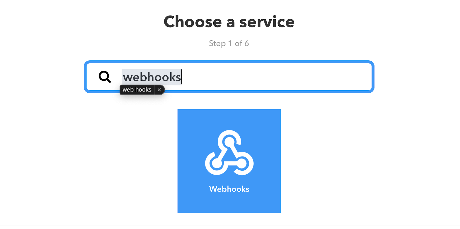
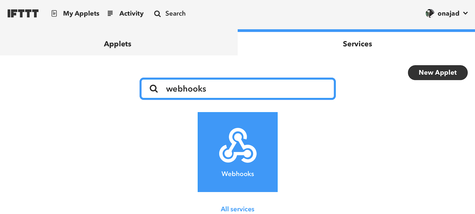
- From “choose a service” page, search for webhooks and click on it.
- Then “choose trigger” page will open.
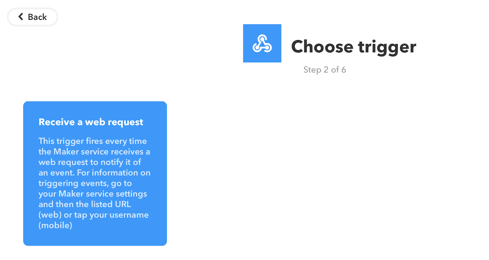
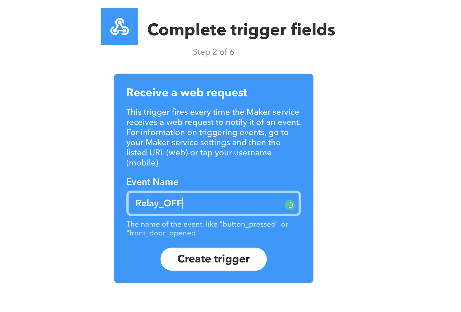
- From “choose trigger” page click on Receive a web request.
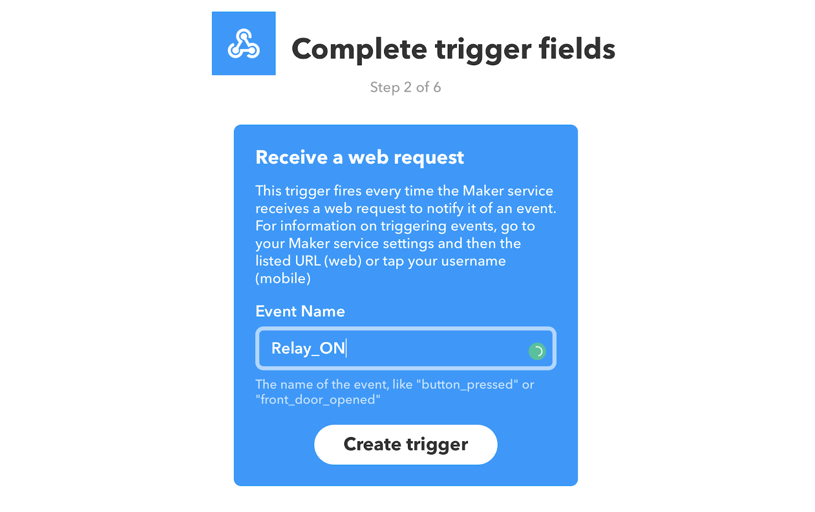
- Now in event name write Relay_ON.
- and click create trigger button.

- Now, choose +that button.
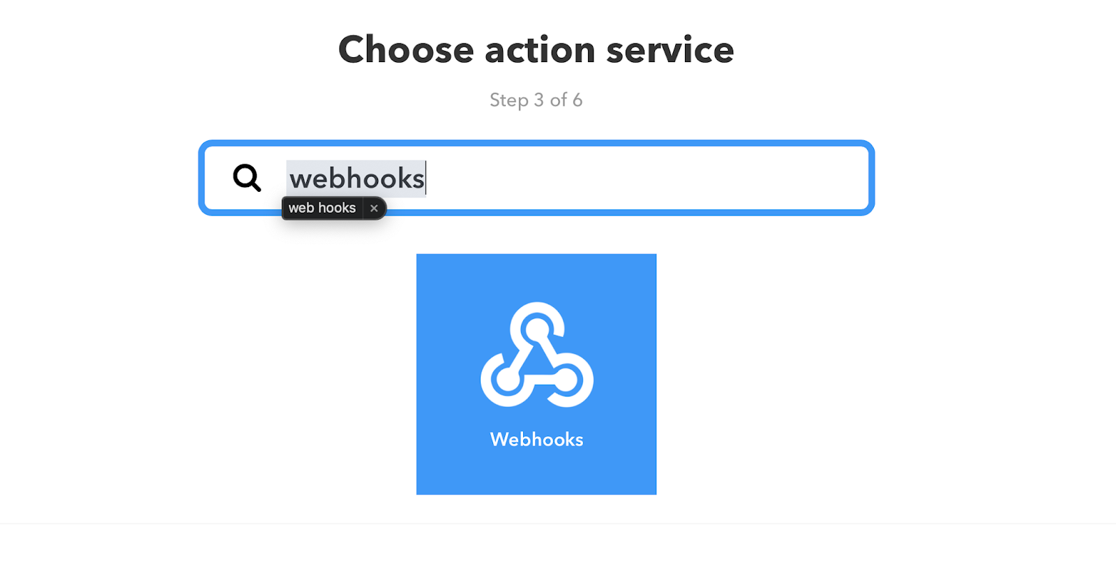
- Then like before, search for webhooks and click on it.
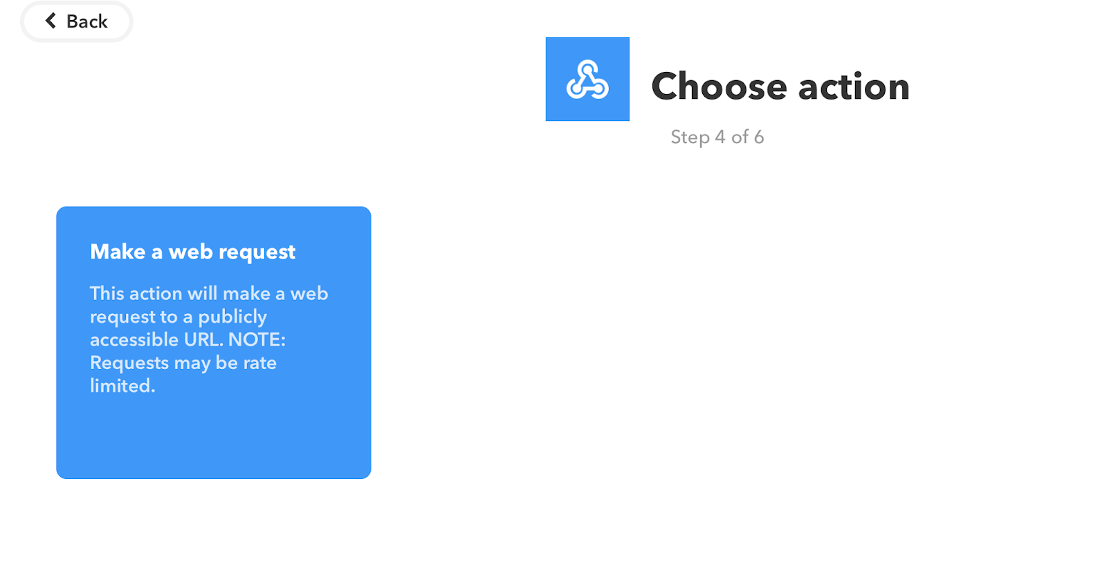
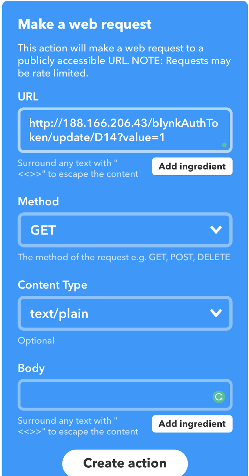
- Now from “choose action” click on Make a web request.
- and fill the details as shown below.
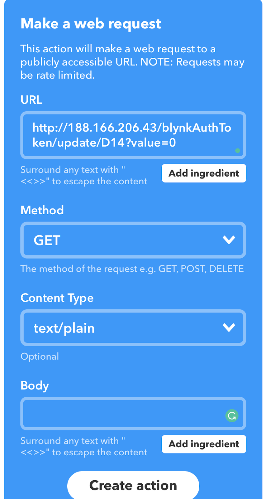
- URL: In this filed paste the HTTP request link which is created before, don’t forget to edit the URL with your blynk Auth Token.
- Method: From the drop-down list choose GET.
- Content/Type: Choose text/plain from the dropdown list.
- Body: Leave it blank.
- Now, Click Create action Button.
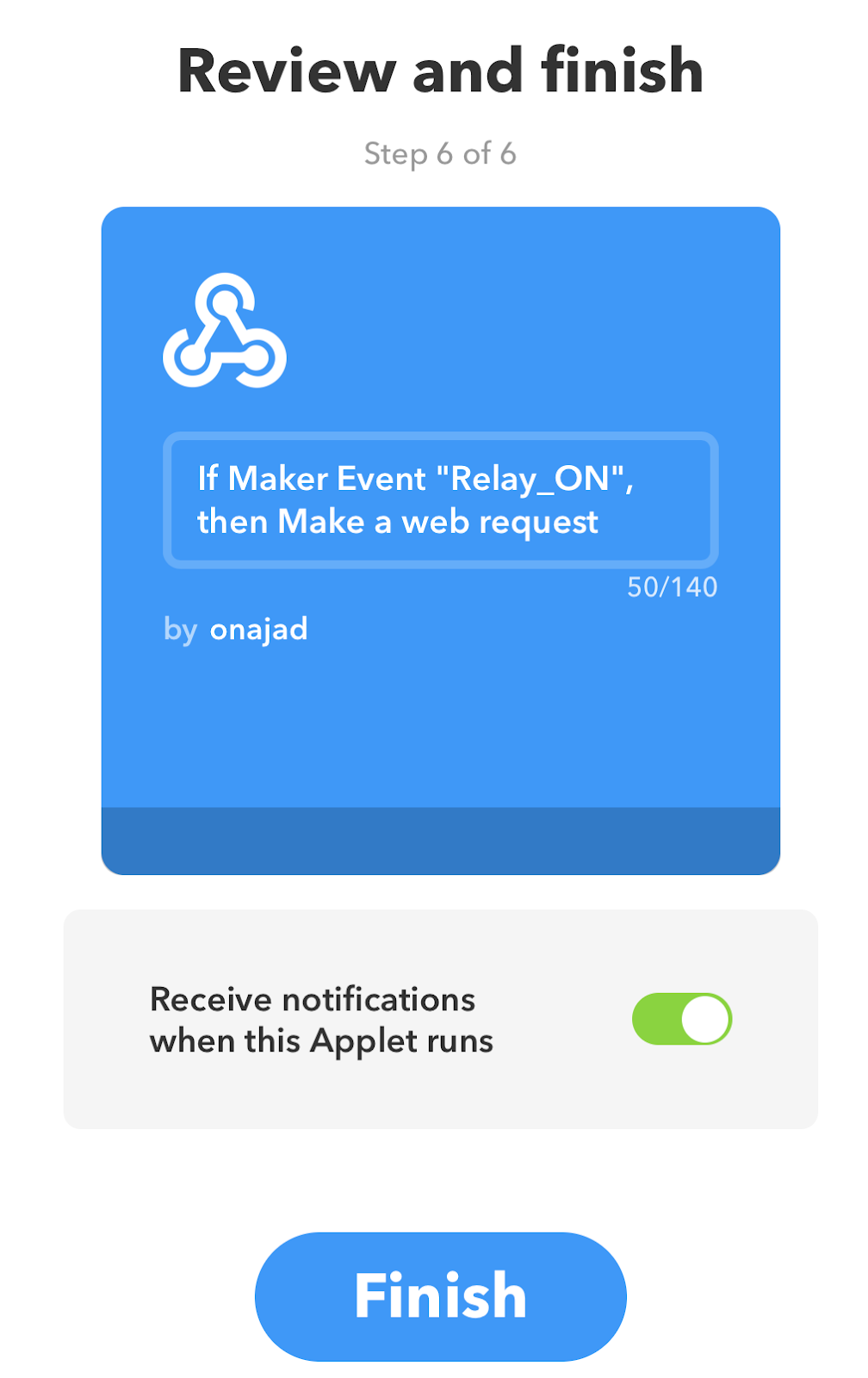
- Now we have successfully created an applet for turning the relay ON.
- like the same way, we need to create another applet for turning OFF the relay.
- Below is the screenshot of the two steps which you need to make changes.
- In this applet Write Relay_OFF instead of Relay_ON.
- Paste the HTTP request URL for turning OFF the relay, that is the value=1.
- and click on create action button.
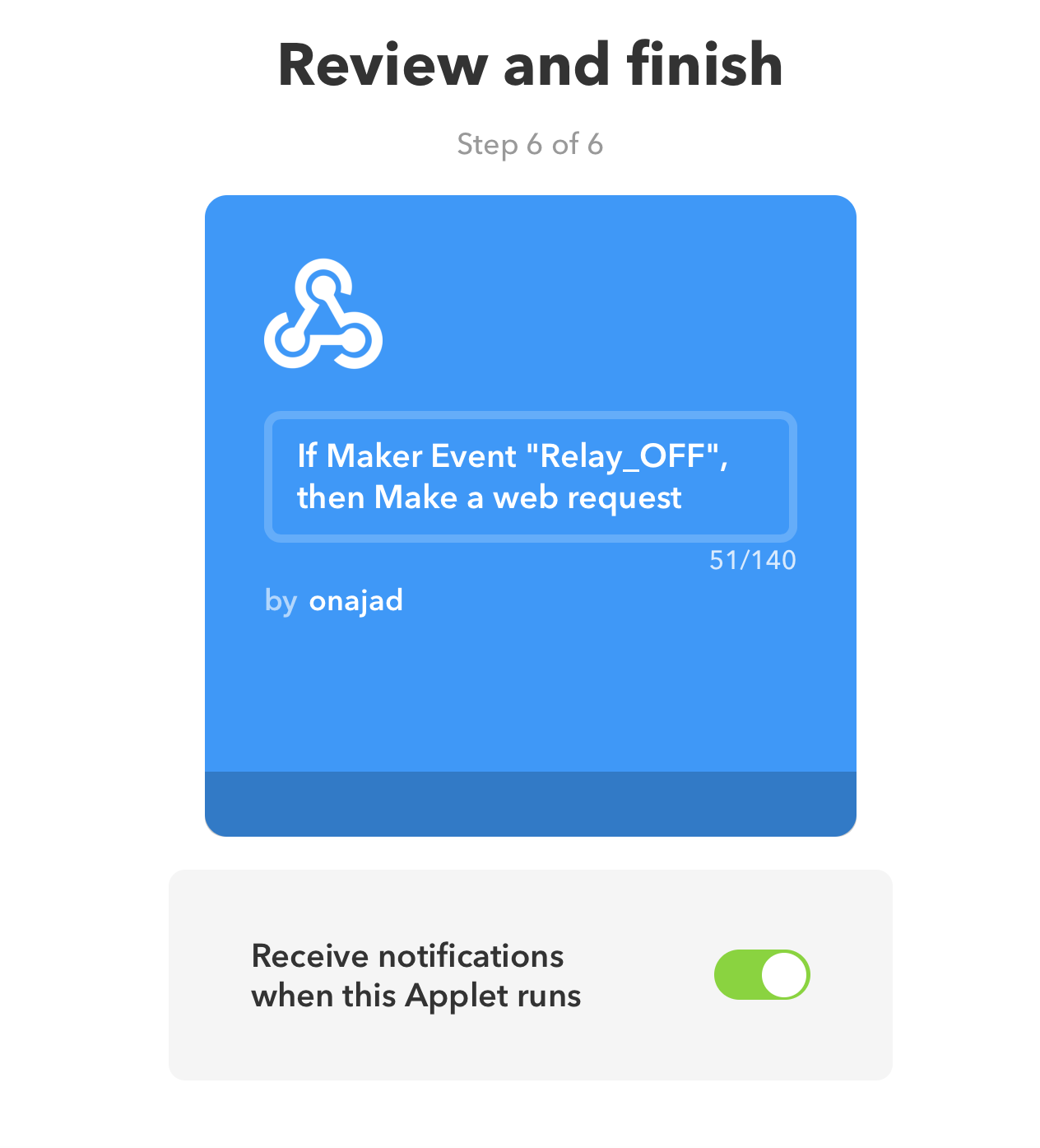
Now we have Successfully created Applets for both Relay ON and Relay OFF.
Step 5: Mi Band 2/3 & Amazfit Сhannel
- Firstly connect your MI band with your phone using the MI Fit android app.
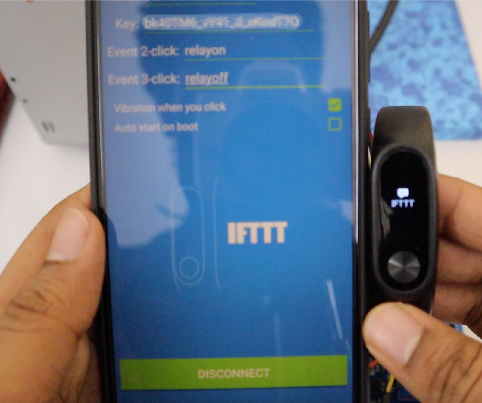
- Now open Mi Band 2/3 & Amazfit Сhannel app from your phone and fill the details as shown below,

- MAC: it will be filled automatically if you have connected the MI band with your phone.
- Event 2 click: Write Relay_ON this is the same event name which we have given in IFTTT applet for Relay_ON.
- Event 3 click: Write Relay_OFF this is the same event name which we have given in IFTTT applet for Relay_ON.
- Key: this is the unique key for your webhooks service, follow the below steps to get your key,
- go to https://ifttt.com/my_services.
- search for webhooks and select it.
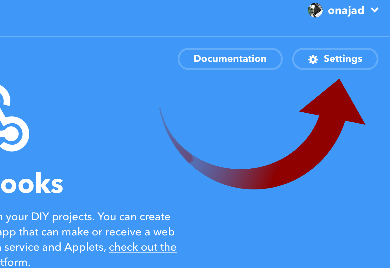
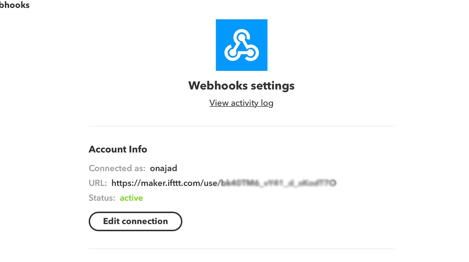
- click on settings, and you can see your key.
- copy and paste it in the Key field in Mi Band 2/3 & Amazfit Сhannel application.
Testing
- Now click on the connect button, if everything is perfect your MI band will vibrate and you can see IFTTT notification on your MI band.
- Now if you double tap on your band the relay will turn ON and if will turn OFF if you triple tap.
Test Video
Full Video Tutorial
To buy electronic components order from UTSOURCE
it is work on miband 4 ?
I have not checked it. if you can please try it and let me know
I need to know If this works with mi band 4!
no, it won’t.