
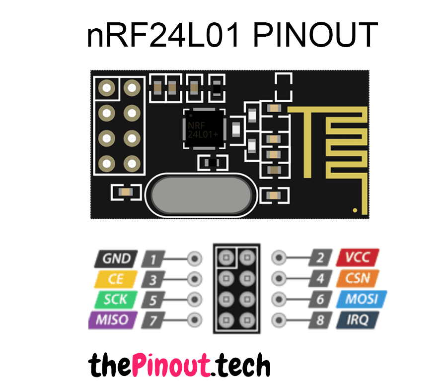
GND is the Ground Pin. It is usually marked by encasing the pin in a square so it can be used as a reference for identifying the other pins.

VCC supplies power for the module. This can be anywhere from 1.9 to 3.9 volts. You can connect it to 3.3V output from your Arduino. Remember connecting it to 5V pin will likely destroy your nRF24L01+ module!
CE (Chip Enable) is an active-HIGH pin. When selected the nRF24L01 will either transmit or receive, depending upon which mode it is currently in.
CSN (Chip Select Not) is an active-LOW pin and is normally kept HIGH. When this pin goes low, the nRF24L01 begins listening on its SPI port for data and processes it accordingly.
SCK (Serial Clock) accepts clock pulses provided by the SPI bus Master.
MOSI (Master Out Slave In) is SPI input to the nRF24L01.
MISO (Master In Slave Out) is SPI output from the nRF24L01.
IRQ is an interrupt pin that can alert the master when new data is available to process.
Reference https://lastminuteengineers.com/