
Introduction
In this tutorial, we are going to learn about how to connect a 12v RGB LED strip with Arduino and how to program to make different color combinations and fading animations.

Things Required
| Components | DIY Usthad | AliExpress | Amazon | Banggood | Utsource |
| Arduino |  | | | ||
| TIP120/TIP122/IRF530 | | | |||
| 1k Resistor | | | |||
| RGB LED Strip | | |
You can use any NPN transistors like TIP120, TIP121, TIP122 of N-Channel MOSFETs like IRF540, IRF 530, based on your application you can change the transistors. the difference is that they have a different collector-emitter current rating. For example, if you are using a large length of RGB LED strip then to drive them you will be needing high current transistors like IRF540 which have Drain Current (Id): 28 Amps. Or if you need only a few LEDs then you can use any other NPN transistors like TIP120 which have Collector Current of 5 Amps continuous and 8 Amps peak
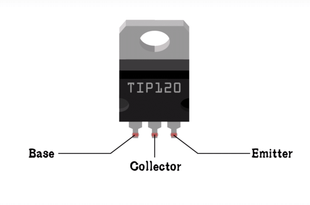
In this tutorial, I am using TIP120 and the pinout diagram is shown below. You can download the datasheet from here.
Pinout – TIP120
Circuit
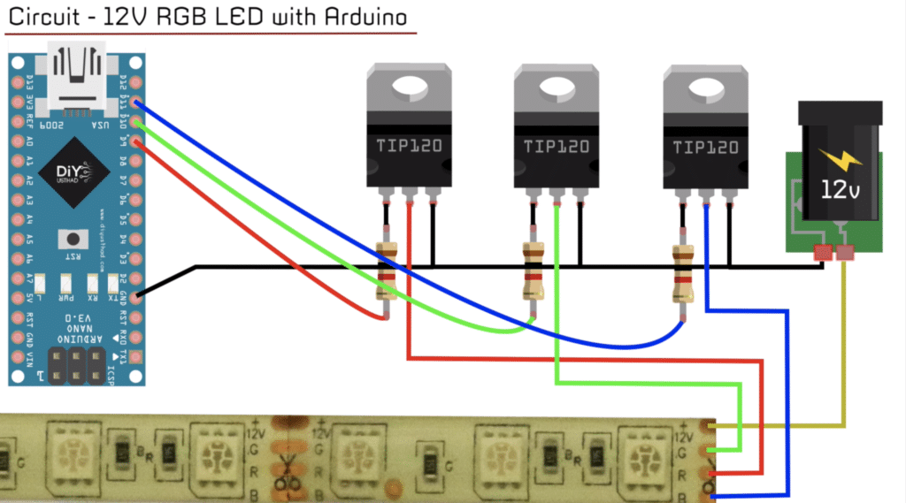
- Connect the emitter of all the transistors to the Ground of Arduino.
- Connect the Ground of 12V power supply to the Ground of Arduino.
- Connect the positive terminal of the 12V power supply to the 12V pin of the RGB LED strip.
- Connect 1 K resistor to the base of each transistor as shown.
- Connect wires from the digital pins D9, D10, D11 to the other end of the resistors as shown in the circuit diagram.
- Finally, connect wires from the R, G and B terminals of the RGB LED strip to the collector (middle pin) if the TIP120 transistors as shown.
Complete Video Tutorial
Code
Color Changing Program
//www.diyusthad.com
//www.youtube.com/c/diyusthad

#define red 9
#define green 10
#define blue 11
int t = 500;

void setup()
{

}

void loop()
{
  analogWrite(red, 255);
  delay(t);
  analogWrite(green, 255);
  delay(t);
  analogWrite(blue, 255);
  delay(t);
  analogWrite(red, 0);
  delay(t);
  analogWrite(green, 0);
  delay(t);
}
Fading Program
//www.diyusthad.com
//www.youtube.com/c/diyusthad

#define red 9
#define green 10
#define blue 11
int brightness;
int fadeAmount = 5;

void setup()
{

}

void loop()
{

  analogWrite(red, brightness); //writing brightness value to red
  analogWrite(green, brightness); //writing brightness value to green

  brightness += fadeamount; //increasing brightness value by 5 in each loop

  if (brightness < 0 || brightness > 255 )
  {
    fadeAmount = -fadeAmount; //reversing the direction of fading when brightness reachs 0 or 255
  }
  delay(30); //delaying the speed of fading
}
You might also like…
To buy electronic components order from UTSOURCE
Did you forget the power for the arduino?
That’s commonsense Bob.
Instruction for project worked great! I modified the code to change colors more slowly on a loop and combined RGB to produce white for outdoor light display.
Thanks for the great instructions.
Always welcome
I loved how you provided BOTH written instructions AND a video for visual learners. Very thoughtful.
thanks for your support
I dont know why it dosent light up.. i use tip122
and wired it like you did
Double Check the connections. It should work. If you need further help whatsapp me @ bit.ly/34zPp5W8
Did you have to do any calculations to create this circtuit? How did you know to only use 1k resitiors?
You state that mosfets can be used instead of the TIP120 darlington transistor, do you have a schematic for that as well? I ask because i on hand 3x FQP30N06L Mosfets (32A – 60V)
I have tested it with IRF series MOSFETs.