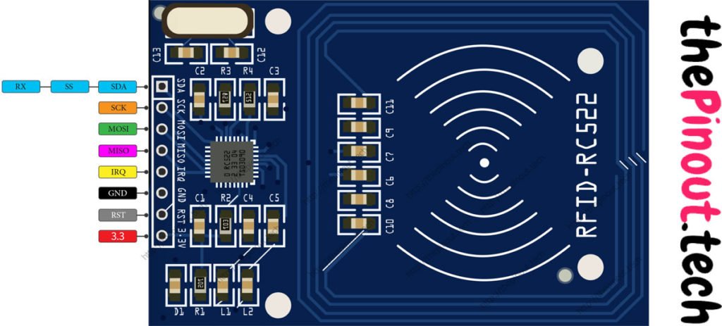

3.3v supplies power for the module. This can be anywhere from 2.5 to 3.3 volts. You can connect it to 3.3V output from your Arduino. Remember connecting it to 5V pin will likely destroy your module!
RST is an input for Reset and power-down. When this pin goes low, hard power-down is enabled. This turns off all internal current sinks including the oscillator and the input pins are disconnected from the outside world. On the rising edge, the module is reset.
GND is the Ground Pin and needs to be connected to GND pin on the Arduino.
IRQ is an interrupt pin that can alert the microcontroller when RFID tag comes into its vicinity.
MISO / SCL / Tx pin acts as Master-In-Slave-Out when SPI interface is enabled, acts as serial clock when I2C interface is enabled and acts as serial data output when UART interface is enabled.
MOSI (Master Out Slave In) is SPI input to the RC522 module.
SCK (Serial Clock) accepts clock pulses provided by the SPI bus Master i.e. Arduino.
SS / SDA / Rx pin acts as Signal input when SPI interface is enabled, acts as serial data when I2C interface is enabled and acts as serial data input when UART interface is enabled. This pin is usually marked by encasing the pin in a square so it can be used as a reference for identifying the other pins.
Credits: https://lastminuteengineers.com

