
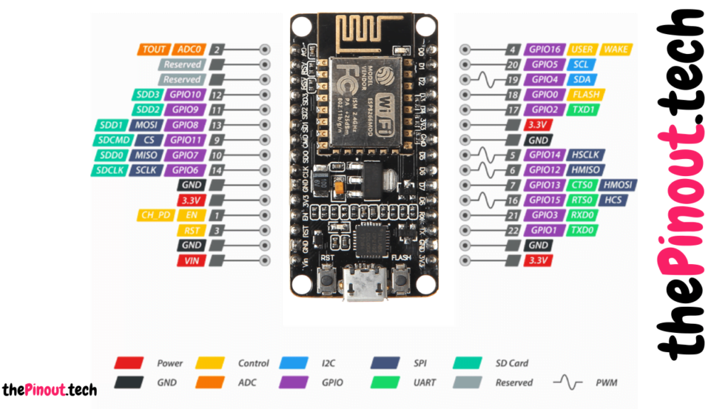
Power Pins There are four power pins viz. one VIN pin & three 3.3V pins. The VIN pin can be used to directly supply the ESP8266 and its peripherals, if you have a regulated 5V voltage source. The 3.3V pins are the output of an on-board voltage regulator. These pins can be used to supply power to external components.

GND is a ground pin of ESP8266 NodeMCU development board.
I2C Pins are used to hook up all sorts of I2C sensors and peripherals in your project. Both I2C Master and I2C Slave are supported. I2C interface functionality can be realized programmatically, and the clock frequency is 100 kHz at a maximum. It should be noted that I2C clock frequency should be higher than the slowest clock frequency of the slave device.
GPIO Pins ESP8266 NodeMCU has 17 GPIO pins which can be assigned to various functions such as I2C, I2S, UART, PWM, IR Remote Control, LED Light and Button programmatically. Each digital enabled GPIO can be configured to internal pull-up or pull-down, or set to high impedance. When configured as an input, it can also be set to edge-trigger or level-trigger to generate CPU interrupts.
ADC Channel The NodeMCU is embedded with a 10-bit precision SAR ADC. The two functions can be implemented using ADC viz. Testing power supply voltage of VDD3P3 pin and testing input voltage of TOUT pin. However, they cannot be implemented at the same time.
UART Pins ESP8266 NodeMCU has 2 UART interfaces, i.e. UART0 and UART1, which provide asynchronous communication (RS232 and RS485), and can communicate at up to 4.5 Mbps. UART0 (TXD0, RXD0, RST0 & CTS0 pins) can be used for communication. It supports fluid control. However, UART1 (TXD1 pin) features only data transmit signal so, it is usually used for printing log.
SPI Pins ESP8266 features two SPIs (SPI and HSPI) in slave and master modes. These SPIs also support the following general-purpose SPI features:
- 4 timing modes of the SPI format transfer
- Up to 80 MHz and the divided clocks of 80 MHz
- Up to 64-Byte FIFO
SDIO Pins ESP8266 features Secure Digital Input/Output Interface (SDIO) which is used to directly interface SD cards. 4-bit 25 MHz SDIO v1.1 and 4-bit 50 MHz SDIO v2.0 are supported.
PWM Pins The board has 4 channels of Pulse Width Modulation (PWM). The PWM output can be implemented programmatically and used for driving digital motors and LEDs. PWM frequency range is adjustable from 1000 μs to 10000 μs, i.e., between 100 Hz and 1 kHz.
Control Pins are used to control ESP8266. These pins include Chip Enable pin (EN), Reset pin (RST) and WAKE pin.
- EN pin – The ESP8266 chip is enabled when EN pin is pulled HIGH. When pulled LOW the chip works at minimum power.
- RST pin – RST pin is used to reset the ESP8266 chip.
- WAKE pin – Wake pin is used to wake the chip from deep-sleep.
Credit: https://lastminuteengineers.com/