
Introduction
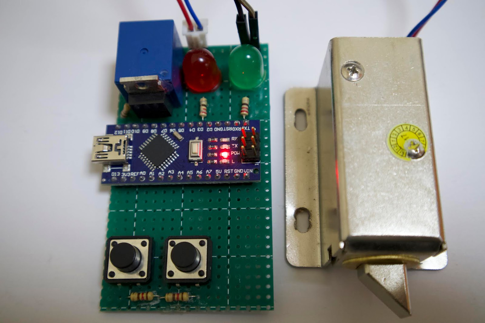
In this project, we are making a pattern lock using Arduino and Solenoid lock. The lock will only get opened when the correct pattern is entered. the pattern is a combination of “long” and “short” press of the pattern switch.

Hardware Used
| Components | AliExpress | Banggood | Amazon.com | Amazon.in | Win Source |
| Micro push-button | |||||
| Arduino Nano | |||||
| TIP120 transistor |  | ||||
| Resistors 2.3k,10k(kit) | |||||
| 1N4007 Diode | |||||
| Solenoid Lock |
Watch the video
Theory
- The code will constantly monitor the enter switch and patter switch state and store it
- Whenever I press the pattern button, the time from millis() function will be stored in two variables, one for press time and one for release time.
- then the time difference between the release and press will be calculated and stored.
- then using an if condition the program will check whether the time difference is less-than or greater-than the predefined time for “short” and “long” press.
- then the code will check whether there is any space for the last detected press and if will be stored to the nearly available NULL space in the pattern lock array until all the array is filled
- now if we press the enter button the program will compare the default pattern and the patter which you just entered.
- if the pattern is true then the transistor will turn on and all the values stored to the pattern array will be erased.
- if the pattern is false then the transistor will remain off and all the values stored to the pattern array will be erased.
- also, I have added some LEDs for indication

Circuit
Connect the Circuit as shown,
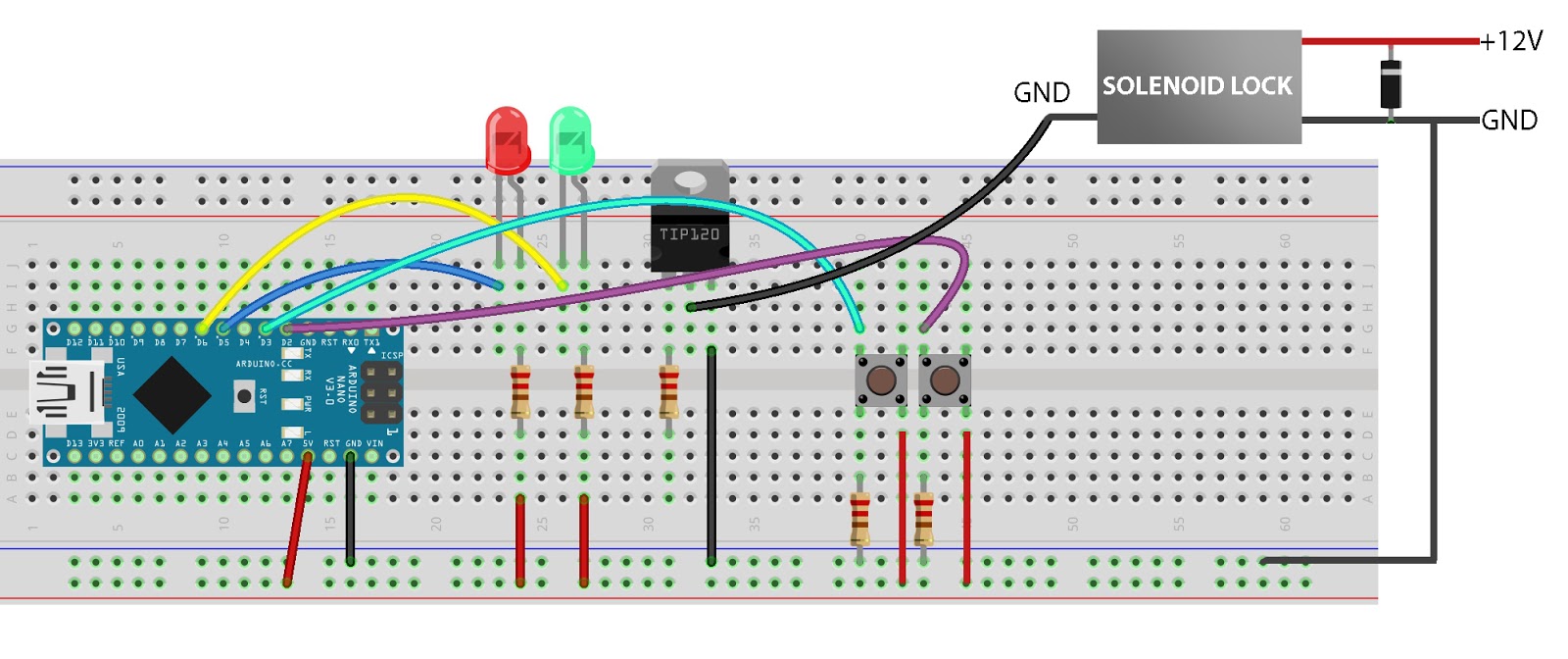
- Digital pin 2 and 3 to enter and the pattern button.
- Digital pin 5 and 6 for Red and Green LEDs.
- Digital pin 12 to the transistor base.
- Transistor emitter to GND.
- Transistor collector to Solenoid ground.
- 12v to Solenoid VCC.
- Don’t forget to connect ground of 12 to ground of Arduino
- The diode in between VCC and ground of solenoid
- and don’t forget all the resistors.
Arduino Code
//https://diyusthad.com

#define pSw 2 //pattern switch pin
#define enter 3 //enter switch pin
#define redLED 5 //red led pin
#define greenLED 6 //green led pin
#define lock 12 //transistor pin
int pattern[4] = {NULL, NULL, NULL, NULL};
int pcode[4] = {1, 2, 2, 1}; //Enter your code 1 for short press and 2 for long press
double presstime = 0, releasetime = 0; //for saving press and release time
double timediff; //for storing time diffrence
bool flag1 = 1, flag2 = 0; //flag values
bool enterSwStatus; //for storing enter switch status
bool patternSwStatus; // for storing patern switch status

void setup() {

  pinMode(pSw, INPUT);
  pinMode(enter, INPUT);
  pinMode(redLED, OUTPUT);
  pinMode(greenLED, OUTPUT);
  pinMode(lock, OUTPUT); digitalWrite(lock, LOW);
  Serial.begin(115200);

  digitalWrite(redLED, LOW);
  delay(100);
  digitalWrite(redLED, HIGH);
  digitalWrite(greenLED, LOW);
  delay(100);
  digitalWrite(greenLED, HIGH);

}

void loop() {

  if (digitalRead(pSw) == 1 && flag2 == 0)
  {
    presstime = millis();
    flag1 = 0;
    flag2 = 1;
    delay(10);
  }
  if (digitalRead(pSw) == 0 && flag1 == 0)
  {
    releasetime = millis();
    flag1 = 1;
    delay(10);
    timediff = releasetime - presstime;

    if (timediff <= 250)
    {
      Serial.println("short");
      digitalWrite(redLED, LOW);
      delay(10);
      digitalWrite(redLED, HIGH);
      flag2 = 0;
      flag1 = 1;
      while (true)
      {
        if (pattern[0] == 0)
        {
          pattern[0] = 1;
          break;
        }
        if (pattern[1] == 0)
        {
          pattern[1] = 1;
          break;
        }
        if (pattern[2] == 0)
        {
          pattern[2] = 1;
          break;
        }
        if (pattern[3] == 0)
        {
          pattern[3] = 1;
          break;
        }
        break;
      }

    }
    else if (timediff >= 250)
    {
      Serial.println("long");
      digitalWrite(redLED, LOW);
      delay(10);
      digitalWrite(redLED, HIGH);
      flag2 = 0;
      flag1 = 1;
      while (true)
      {
        if (pattern[0] == 0)
        {
          pattern[0] = 2;
          break;
        }
        if (pattern[1] == 0)
        {
          pattern[1] = 2;
          break;
        }
        if (pattern[2] == 0)
        {
          pattern[2] = 2;
          break;
        }
        if (pattern[3] == 0)
        {
          pattern[3] = 2;
          break;
        }
        break;
      }
    }
    patternSwStatus = 1;
  }


  if (digitalRead(enter) > 0 && enterSwStatus == 0)
  {
    enterSwStatus = 1;
    for (int i = 0; i < 4; i++)
    {
      Serial.print(pattern[i]);
    }
    Serial.println("");
    if (unlock() == false)
    {
      Serial.println("wrong");
      digitalWrite(redLED, LOW);
      delay(200);
      digitalWrite(redLED, HIGH);
    }
    else
    {
      Serial.println("access granted");
      digitalWrite(greenLED, LOW);
      digitalWrite(lock, HIGH);
      delay(10000);
      digitalWrite(greenLED, HIGH);
      digitalWrite(lock, LOW);
    }
    patternSwStatus = 0;
    pattern[0] = NULL;
    pattern[1] = NULL;
    pattern[2] = NULL;
    pattern[3] = NULL;
  }
  if (digitalRead(enter) == 0)
    enterSwStatus = 0;

}
int unlock()
{
  if (pcode[0] != pattern [0])
    return false;
  else if (pcode[1] != pattern [1])
    return false;
  else if (pcode[2] != pattern [2])
    return false;
  else if (pcode[3] != pattern [3])
    return false;
  else
    return true;
}
How to change the LOCK CODE?
int pcode[4] = {1, 2, 2, 1};
Enter your code “1” for short press and “2” for long press in the above-mentioned line.
For example, if you want to set your code as “long short short short” then change the line to this ????????
int pcode[4] = {2, 1, 1, 1};