


In this tutorial we are going to learn about Interfacing 7 segment display with an Arduino, There are two types of 7 segment displays available in the market so we will be learning how they differ when we interface them with Arduino.
- Common Anode Display
- Common Cathode Display
So lets learn to interface both Common Anode & Common Cathode display with an Arduino development board.
All about 7 segment display
Read more about 7-Segment Displays and how they work in the below article
Components Needed
| Components | AliExpress | Banggood |
|---|---|---|
| Arduino UNO or |  | |
| Arduino Nano | | |
| 7 Segment (common anode) | | |
| 7 Segment (common cathode) | | |
| Breadboard | | |
| Jumper wire | | |
| Resistor Kit 1/4 watt | | |


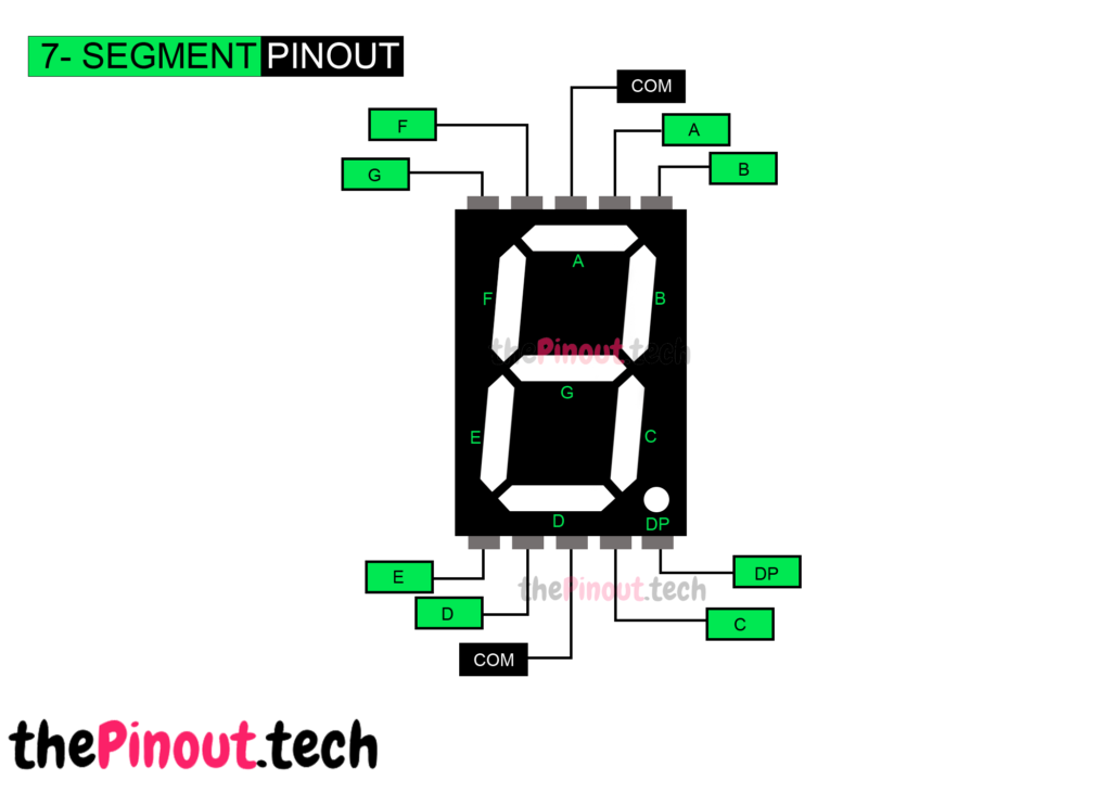
7 Segment Display Pinout
Now let’s go over the segment configuration so we know which pins light up which segments. The pinout for the 7-segment display is as follows.

Installing Library
Before you can start writing code to use the 7-segment displays, we need to download the SevSeg Arduino Library. We can download it by visiting the GitHub repo and manually install the library or, just click this button to download the zip file.

To install it, open the Arduino IDE, go to Sketch > Include Library > Add .ZIP Library, and then select the SevSeg ZIP file that we just downloaded.
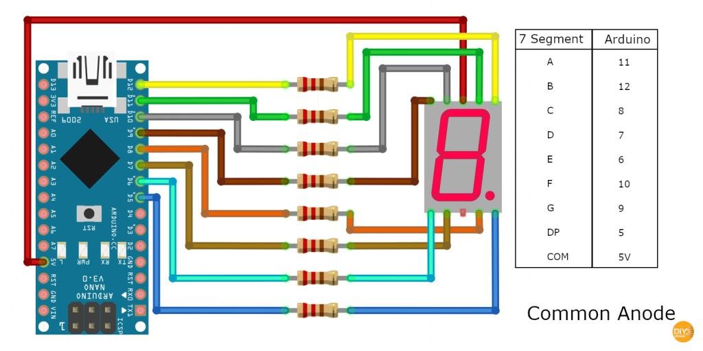
Common Anode Display
In this type of display, all the anode connections of the LED segments are connected together 5v. The separate segments are lightened by connecting them to the ground.
Now let’s connect one of the common pins 3 or 8 to the 5V pin on the Arduino. Rest 4 pins on the lower position are connected to digital pin 5 to digital pin 8. The other 4 pins on the upper position are connected to digital pin 9 to 12 as shown in the below circuit diagram.
Circuit

Notice
The display may work without current limiting resistors, it’s always a good idea to have them in your circuit to avoid damaging your display.
Code
For testing we can write a small Arduino code to display digits 0 to 9 with one second interval between them
#include "SevSeg.h"
SevSeg sevseg;

void setup()
{
	//Set to 1 for single digit display
	byte numDigits = 1;

	//Defines pin connections in order: A, B, C, D, E, F, G, DP
	byte segmentPins[] = {11, 12, 8, 7, 6, 10, 9, 5};
	bool resistorsOnSegments = true;

	sevseg.begin(COMMON_ANODE, numDigits, digitPins, segmentPins, resistorsOnSegments);
	sevseg.setBrightness(90);
}

void loop()
{
   //Display numbers one by one with 1 seconds delay
   for(int i = 0; i < 10; i++)
   {
     sevseg.setNumber(i);
     sevseg.refreshDisplay();
     delay(1000);
   }
}
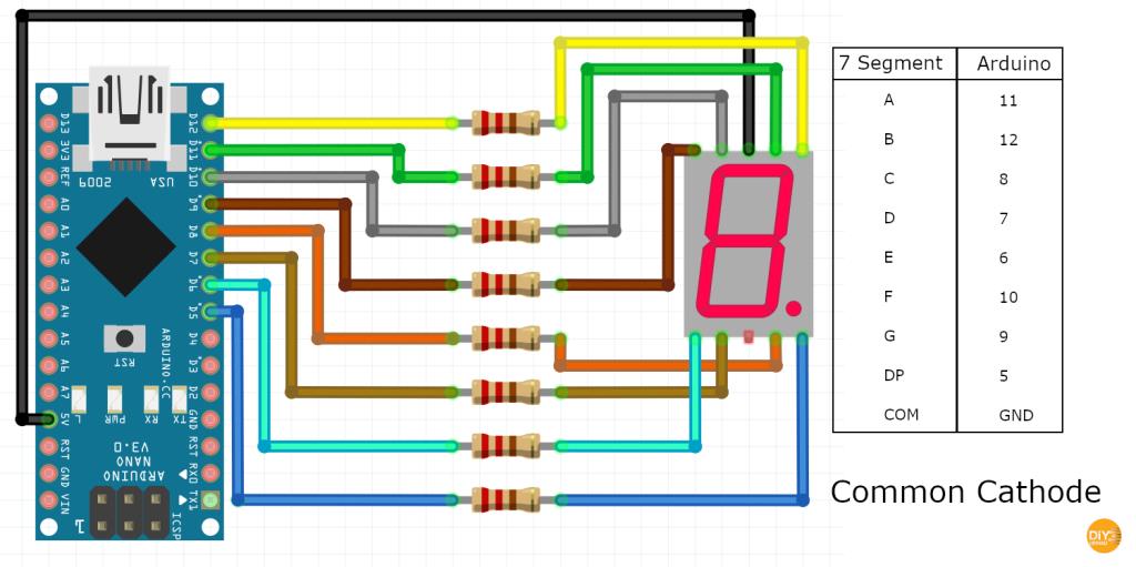
Common Cathode Display
In this type of display, all the cathode connections of the LED segments are connected together to the ground. The separate segments are lightened by applying the required voltage.
Now let’s connect one of the common pins 3 or 8 to the GND pin on the Arduino. Rest 4 pins on the lower position are connected to digital pin 5 to digital pin 8. The other 4 pins on the upper position are connected to digital pin 9 to 12 as shown in the below circuit diagram.
Circuit
Notice
The display may work without current limiting resistors, it’s always a good idea to have them in your circuit to avoid damaging your display.
Code
For testing Common Cathode also we can write a small Arduino code to display digits 0 to 9 with a one-second interval between them.
#include "SevSeg.h"
SevSeg sevseg;

void setup()
{
	//Set to 1 for single digit display
	byte numDigits = 1;

	//Defines pin connections in order: A, B, C, D, E, F, G, DP
	byte segmentPins[] = {11, 12, 8, 7, 6, 10, 9, 5};
	bool resistorsOnSegments = true;

	sevseg.begin(COMMON_CATHODE, numDigits, digitPins, segmentPins, resistorsOnSegments);

	sevseg.setBrightness(90);
}

void loop()
{
   //Display numbers one by one with 1 seconds delay
   for(int i = 0; i < 10; i++)
   {
     sevseg.setNumber(i);
     sevseg.refreshDisplay();
     delay(1000);
   }
}
