Introduction
In this project, we will learn how to make IoT Based Home Automation Project using Google Firebase, ESP8266 – 01 & Atmega328p. Home Automation means controlling home appliances like lights, fans, or anything with internet-connected relays.
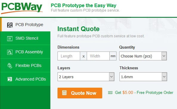
This project is sponsored by PCBWay. PCB Way offers various PCB prototyping and manufacturing services, including this FR-4 PCBs, rigid-flex PCBs, aluminum PCBs, and PCBs with dozens of layers. PCBWay also provides turnkey PCB assembly services to assist you in populating your PCBs. Recently they have introduced an Online Rapid Prototyping service that includes CNC machining, Sheet metal fabrication, 3D printing, and Injection molding check them out on their website.

Video

Earlier we learned about Home automation using Blynk Application, WebServer. In this project we will use Google Firebase.
Google Firebase is a Google-backed application development software used for creating, managing, and modifying data generated from any android/IOS application, web services, IoT sensors & Hardware. To learn more about the Google Firebase Console, you can read the official Google Firebase Documentation from Google Firebase.
We will also learn to design a Home Automation Android Application using Kodular.io. Using the Firebase Host & Authentication Key, we will connect the Android Application and ESP8266-01 with Google Firebase Realtime Database. So whenever we turn ON/OFF the switches from the App the changes will be updated in the Firebase Database and our ESP8266-01 will be able to read any changes in the Firebase Database then the data will be transmitted to Atmega328 via UART then Atmega328 will toggle the GPIO Pins thus turning ON/OFF the appliances connected to Relay.
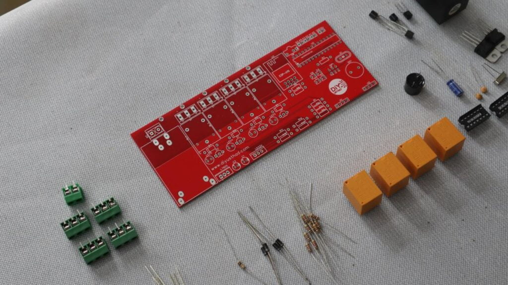
Hardware’s Required
| Components | Quantity | AliExpress | Amazon.com |
|---|---|---|---|
| ESP8266 01 | 1 | ||
| 12v Relay | 4 |  | |
| Atmega328p | 1 | | |
| LM7805 | 1 | ||
| BC547 | 4 | ||
| 1N4007 | 4 | | |
| Capacitor 63v 10uF | 2 | ||
| Capacitor 22pF | 2 | ||
| Resistor kit (1k ,2.2k) | |||
| 16 MHz Crystal | 1 | ||
| Header pins (male & female) | |||
| LD33V | 1 | | |
| LED | 4 | ||
| Screw Terminal 1×3 | 4 | | |
| Screw Terminal 1×2 | 1 | ||
| PCB | 1 |


Software & Libraries Needed
- Arduino IDE with ESP8266 board package installed. – Detailed Instructions.
- FirebaseESP8266 Library – Download

- Google account – For creating a Firebase project.

Setting up Firebase
Step 1: If you have a Gmail id then you are already Sign Up for Firebase. But if you don’t have a Gmail id then first Sign Up for Gmail: https://gmail.com/
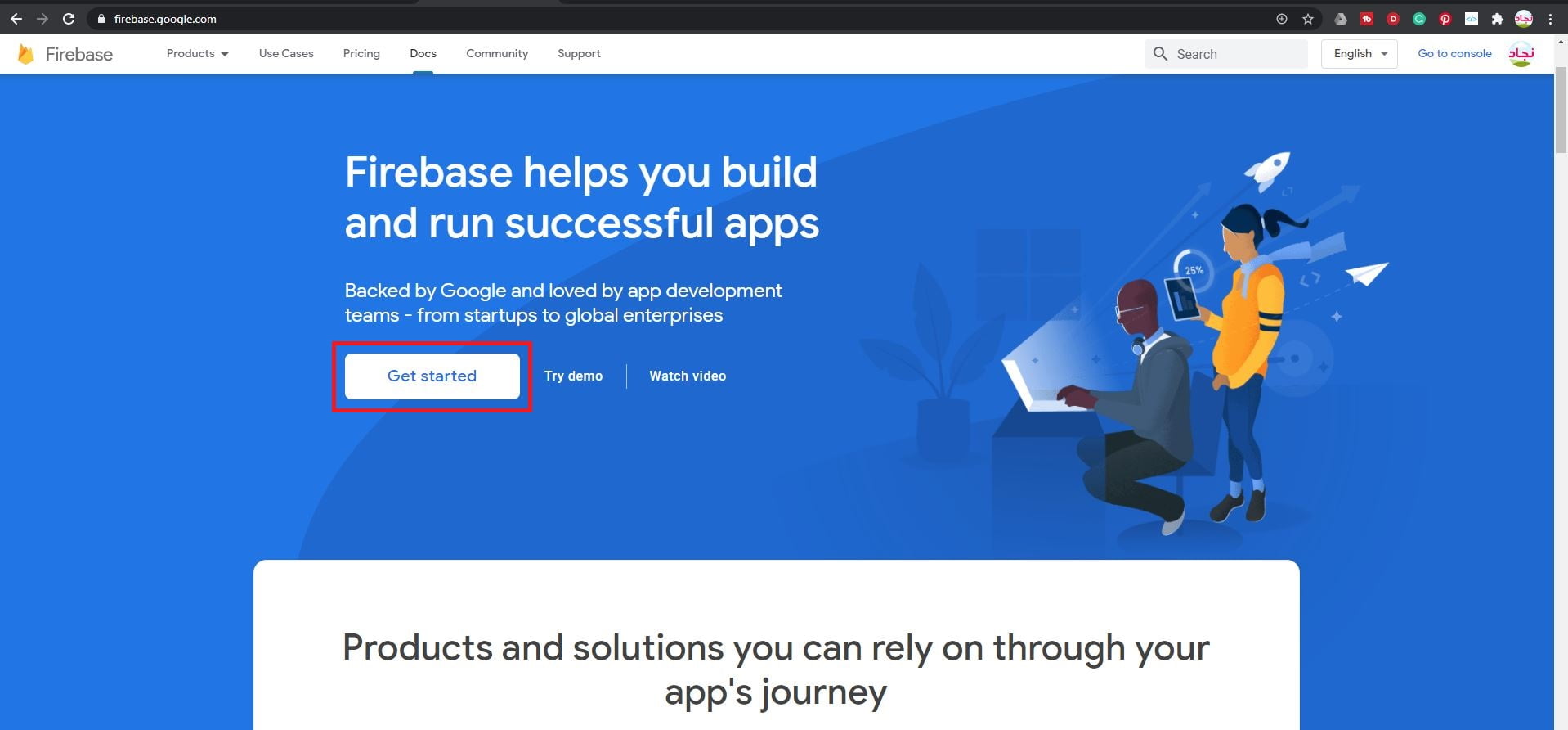
Step 2:Now visit https://firebase.google.com/ and click on Get Started.
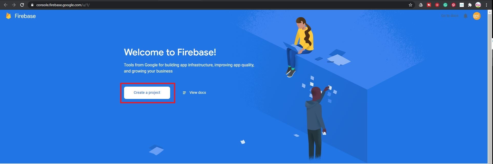
Step 3: Click on “Create a Project”.
Step 4:
- Give a name for your project, in this case, I’m giving “HomeAutomation“.
- Accept the Firebase terms.
- Click Continue.

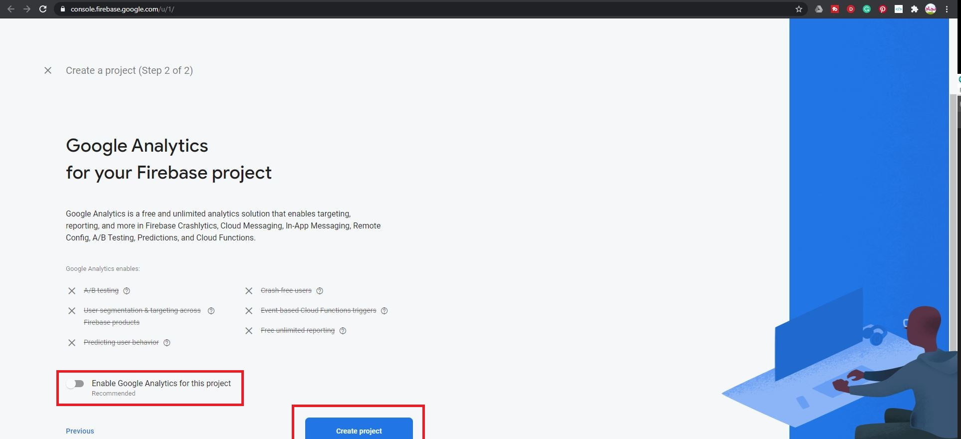
Step 5: Disable google analytics we don’t need that now and click “Create project“.
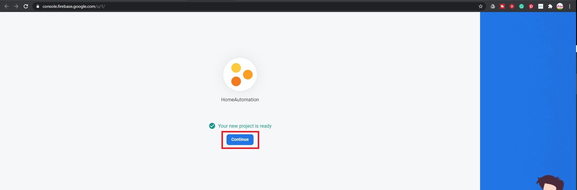
Step 6: Wait for some time until the project is created and click the “Continue” button.
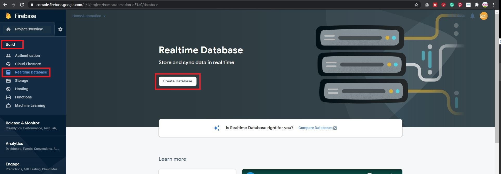
Step 7: Under the “Build” tap select “Realtime Database” and click on “Create database“.
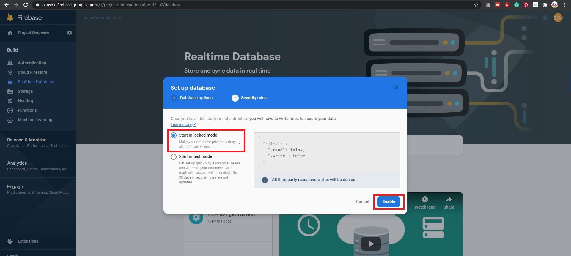
Step 8: Click “Next“.

Step 9: Click on “Enable”
Step 10:
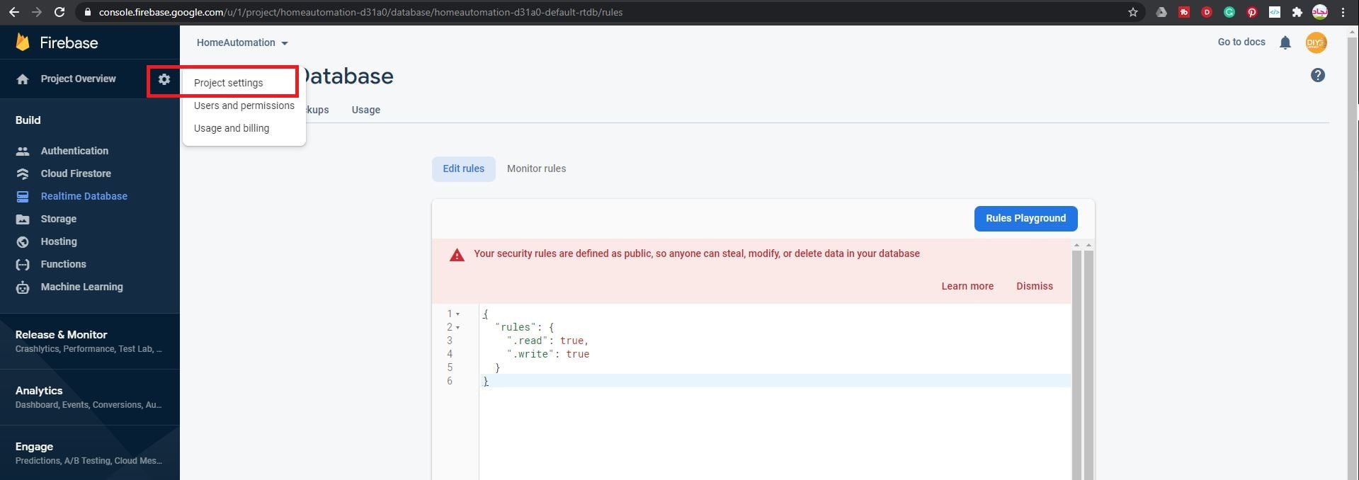
- After the database is created, click on the “Rules” tab and changes the rules as shown below (the read and write is changed to true from false)
- Then click on “Publish“.

Step 11:Now click on “Project Settings“.
Step 12:
- Click in “Service Accounts“.
- Select “Database Secrets” and copy the secret and save it in a notepad we need it in the future.

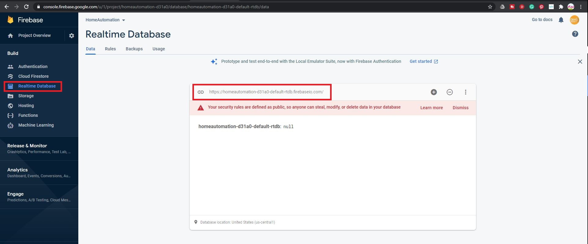
Step 13: Also copy and save the project URL from the “Realtime database“.
Android App Using Kodular.io
Kodular is the best way to make apps with a simple interface and simple code! There are so many components and options, and it has a beautiful Material Design. Kodular was baked from MIT App Inventor to make app coding easier.
Step 1:
- Download the project file from here.

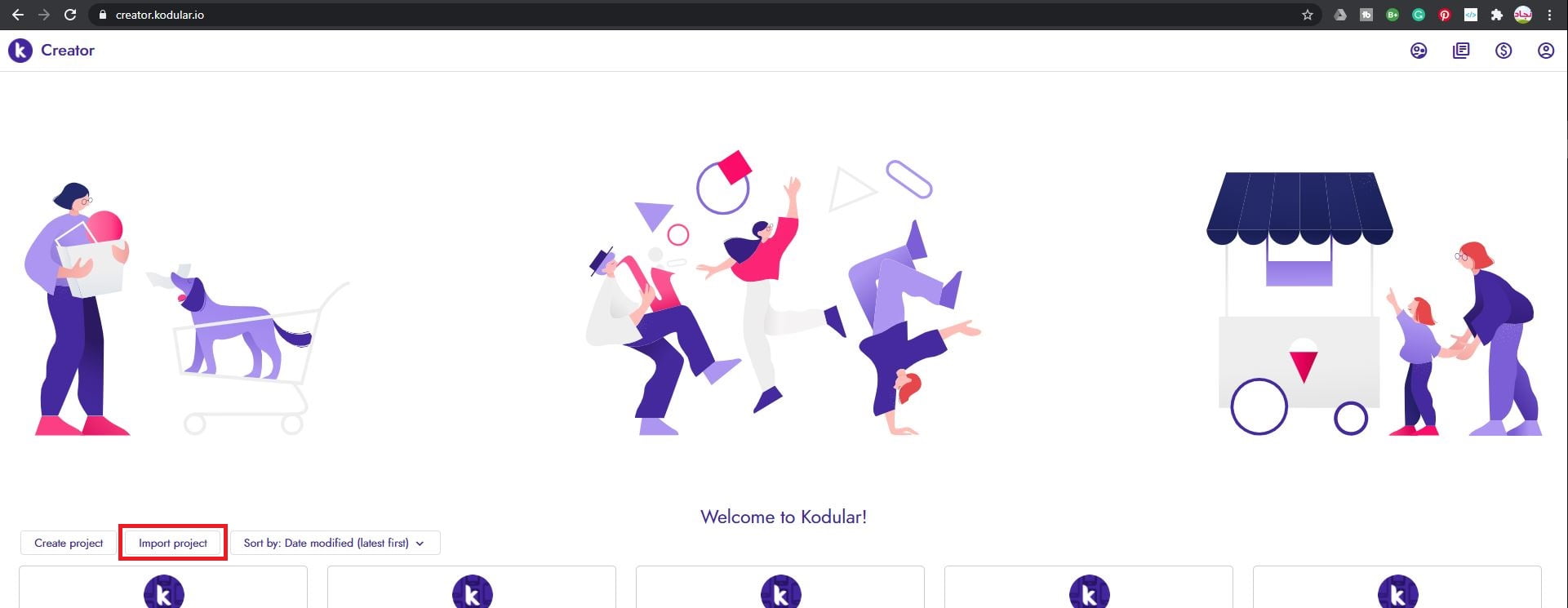
- Then go to create.kodular.io, and signup in if you don’t have an account already
- Then click on Import project.
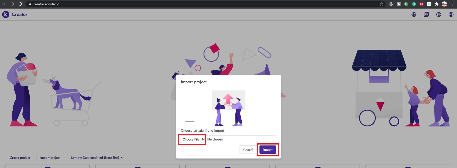
Step 2: Click on Choose File then select the downloaded project file and click Import
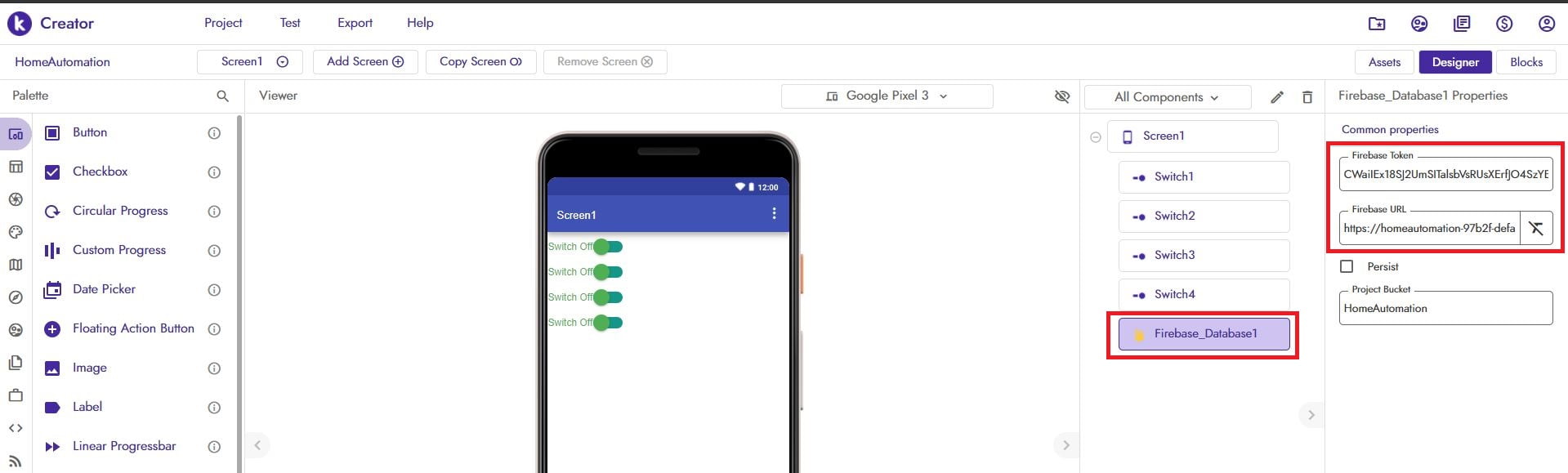
Step 3:
- Now click on the Firebase_Database1 component.
- Then under Firebase_Database1 Properties, paste the firebase database secret to Firebase token and project URL to Firebase URL fields.
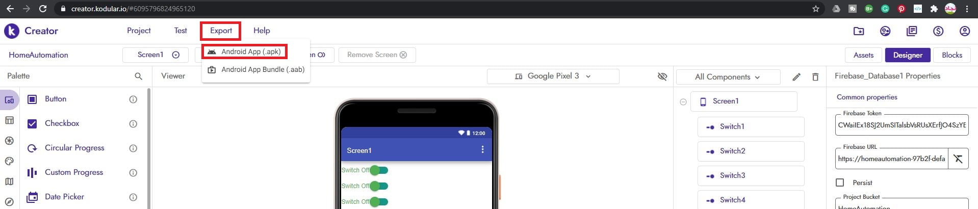
Step 4: Now click on the Export tab and select Android App (.apk). Download the app and install in on your phone.
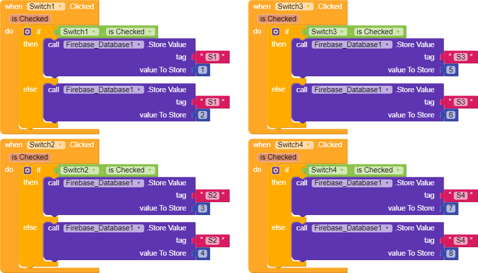
Block Code for Kodular or MIT App Inventor
You can refer the below block code if you are making your own application.
Programming
Code for Atmega328
Upload the below code to the ATmega328 microcontroller.
#define relay1 5
#define relay2 6
#define relay3 7
#define relay4 8
#define buzzer A4

int i = 0;
String relayState;

void setup() {

  pinMode(relay1, OUTPUT);
  pinMode(relay2, OUTPUT);
  pinMode(relay3, OUTPUT);
  pinMode(relay4, OUTPUT);
  pinMode(buzzer, OUTPUT);
  digitalWrite(buzzer, LOW);
  Serial.begin(9600);
}

void loop()
{
  if (Serial.available() > 0)
  {
    Buzzer();
    while (Serial.available())
    {
      relayState = Serial.readString();

      if (relayState == "2")
      {
        digitalWrite(relay1, LOW);
      }
      else if (relayState == "1")
      {
        digitalWrite(relay1, HIGH);

      }

      else if (relayState == "4")
      {
        digitalWrite(relay2, LOW);

      }
      else if (relayState == "3")
      {
        digitalWrite(relay2, HIGH);

      }

      else if (relayState == "6")
      {
        digitalWrite(relay3, LOW);

      }
      else if (relayState == "5")
      {
        digitalWrite(relay3, HIGH);

      }

      else if (relayState == "8")
      {
        digitalWrite(relay4, LOW);

      }
      else if (relayState == "7")
      {
        digitalWrite(relay4, HIGH);

      }
    }
  }
}

void Buzzer()
{
  digitalWrite(buzzer, HIGH);
  delay(30);
  digitalWrite(buzzer, LOW);
}
Code for ESP8266-01
Before uploading the code to ESP8266 you have to change the following
- Paste your Firebase host URL to the below code which we obtained earlier from our Firebase database page
- Paste your database secret to the ESP8266 code where it’s mentioned.
- Also, add your WiFi SSID name and password to the code.
- Now upload the code.
#include "FirebaseESP8266.h"
#include <ESP8266WiFi.h>

#define FIREBASE_HOST "your firebase host url"
#define FIREBASE_AUTH "your firebase database secret" // Your Firebase Database Secret
#define WIFI_SSID "your SSID"                               // your WiFi SSID
#define WIFI_PASSWORD "your wifi password"                      // your WiFi PASSWORD

FirebaseData firebaseData;

String path = "Najad/";

void printResult(FirebaseData &data);

void setup()
{
  Serial.begin(9600);

  WiFi.begin(WIFI_SSID, WIFI_PASSWORD);
  Serial.print("Connecting to Wi-Fi");
  while (WiFi.status() != WL_CONNECTED)
  {
    Serial.print(".");
    delay(300);
  }
  Serial.println();
  Serial.print("Connected with IP: ");
  Serial.println(WiFi.localIP());
  Serial.println();

  Firebase.begin(FIREBASE_HOST, FIREBASE_AUTH);
  Firebase.reconnectWiFi(true);
  Firebase.beginStream(firebaseData, path);
}

void loop()
{
  Firebase.readStream(firebaseData);
  firebaseData.streamTimeout();

  if (firebaseData.streamAvailable())
    Serial.print(firebaseData.stringData());
}
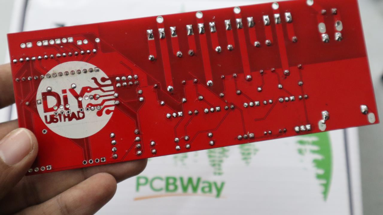
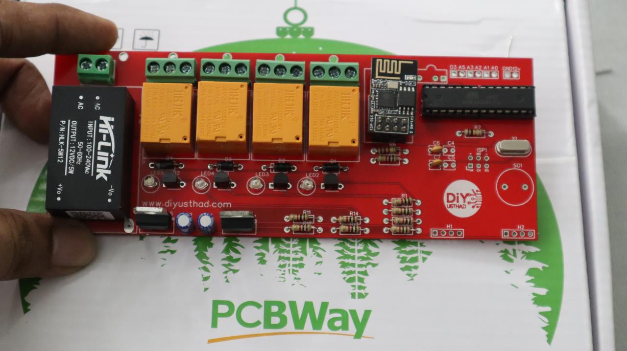
PCB Assembling & Testing
As you can see below we have completed the soldering of all the required components to our PCB. Now let’s insert the Atmega328 and ESP8266-01 in the slots provided and power it ON.