
Today we are going to learn the following about touch switch based on TTP223.
- Pinout explanation
- Four different modes of the touch switch
- Connecting with LED
- Interfacing with Arduino
- Adjusting touch sensitivity
TTP223 Features
- Operating voltage 2.0V~5.5V
- Operating current @VDD = 3V, no load
- At low power mode typical 1.5uA, maximum 3.0uA
- The response time max 220mS at low power mode @VDD=3V
- Sensitivity can adjust by the capacitance(0~50pF) outside
- Stable touching detection of the human body for replacing traditional direct switch key
- Provides Low Power mode
- Provides direct mode、toggle mode by pad option(TOG pin) Q pin is CMOS output
- All output modes can be selected active high or active low by pad option(AHLB pin)
- After power-on have about 0.5sec stable-time, during the time do not touch the keypad, And the function is disabled
- Auto calibration for life.
- At low power mode, the re-calibration period is about 4.0sec normally,
- When key detected touch and released touch, the auto re-calibration will be redoing after about 16sec from releasing key
- The sensitivity of TTP223N-BA6 is better than TTP223-BA6’s. But the stability of TTP223N-BA6 is worse than TTP223-BA6’s.
Hardware Required
| Components | DIY Usthad | Amazon.com | Banggood | AliExpress | Utsource |
|---|---|---|---|---|---|
| Arduino Nano |  | | | | |
| TTP223 Touch Switch | | | | | |
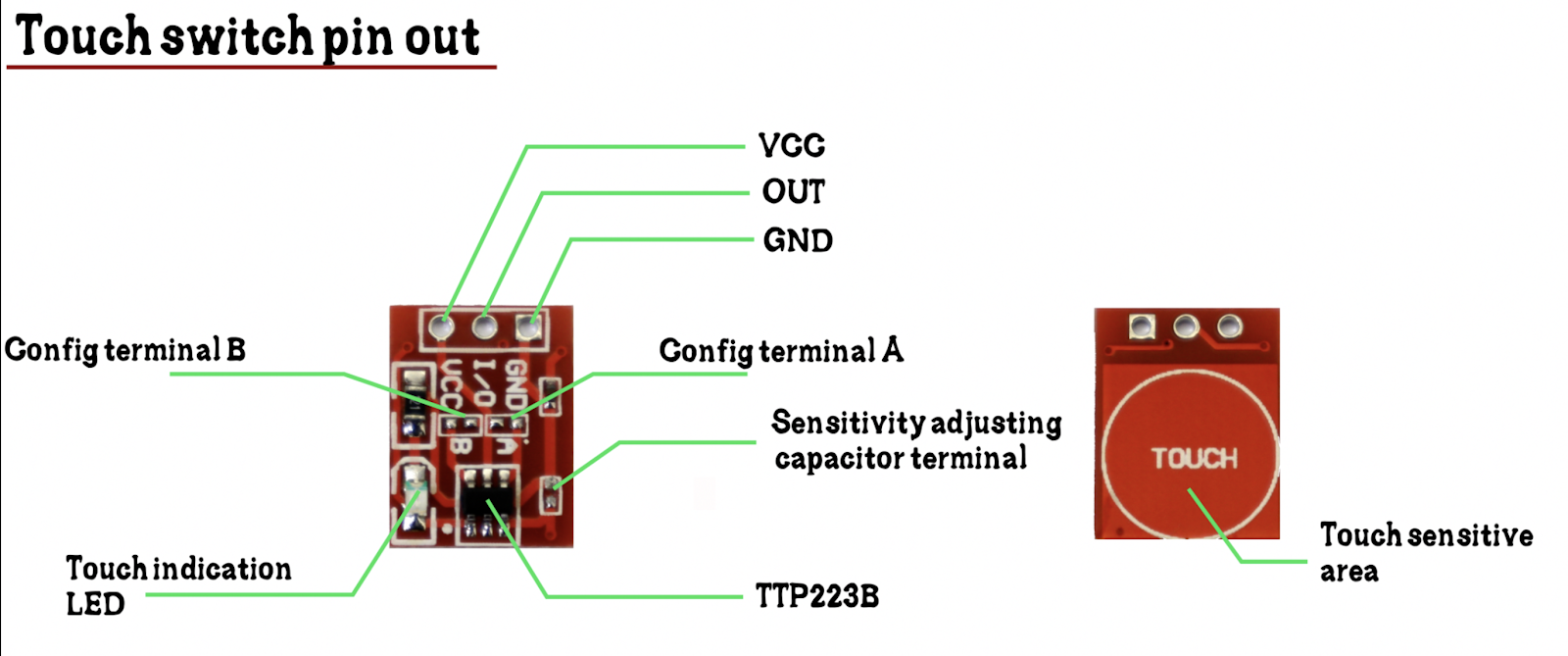
Touch switch configurations

There are four different configurations for this touch switch, which is explained below in details.
Config 1:
- To obtain configuration one both A and B terminals should be in open position.
- Default output state will be LOW
- Changes the state (to HIGH) when a touch is detected and will be back to the default state when touch is released
Config 2:
- To obtain configuration one both A should be open and B should be in close position.
- Default output state will be LOW
- Changes the state when a touch is detected and remains on that state until another touch is detected.
Config 3:
- To obtain configuration one both A should be close and B should be in open position.
- Default output state will be HIGH
- Changes the state (to LOW) when a touch is detected and will be back to the default state when touch is released
Config 4:
- To obtain configuration one both A and B terminals should be close position.
- Default output state will be HIGH
- Changes the state when a touch is detected and remains on that state until another touch is detected.
Adjusting touch sensitivity
Sensitivity can adjust by adding a capacitance, the value of capacitor ranges from 0 to 50 pf, where 0pf gives the full sensitivity and 50pf will gives the lowest sensitivity. For example, if you needed the touch switch to work through glass or acrylic you will need to adjust the sensitivity based on the thickness of the material.
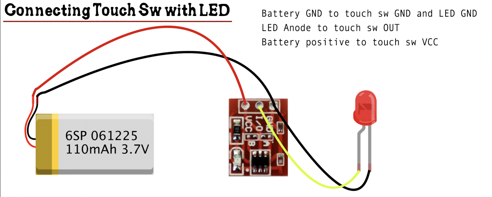
Connecting with LED
Interfacing with Arduino
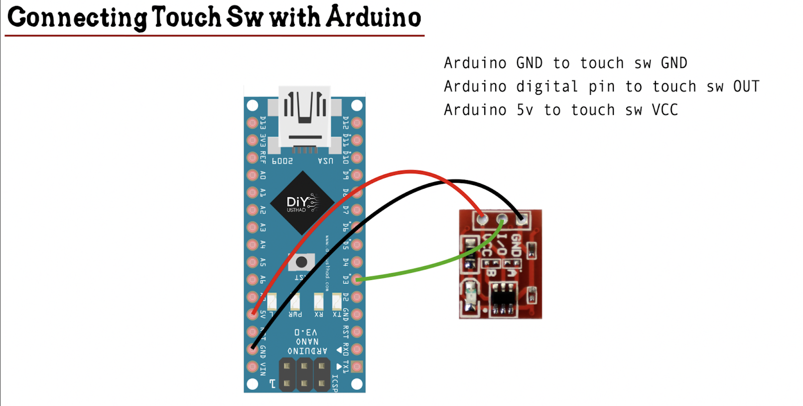
| Arduino | Touch Sw |
|---|---|
| GND | GND |
| 5V | VCC |
| D3 | I/O |
Watch the video to understand it better
Code
//www.diyusthad.com

#define touchSw 4

void setup() {

  pinMode(touchSw,INPUT);

  Serial.begin(9600);

}


void loop() {

  boolean touchState;

  touchState = digitalRead(touchSw);

  Serial.println(touchState);


  if(touchState == HIGH)

  {

    //write statements to execute when the sw is high

  }

  else

  {

    //write statements to execute when the sw is low

  }

}
To buy electronic components order from UTSOURCE
thanks
How to make this circuit work as a Toggle Switch or on/off switch..? I mean, if I touch once..It will be on and if touched again, it will be off. Please help…Thanks
I have bought this blue pcb circuit on line…Gave 5 volts supply and put the load….But it works only as touch to on switch circuit and removal of touch switches it off…This blue PCB has no provision for jumper…
Is this is the touch switch you are talking about?
Yes this one place how can I make it turns toggle because mine is this blue ttp223 and it doesn’t have the confi a and b
Then you have to directly short the IC legs but it’s a difficult task.
Solder B, Keep A Open (those are the jumper positions)
yes they are
Brother how can i connect ttp223 to a 5v bluetooth speaker for power on/off, must reply if anyone can make this circuit, while connecting to bluetooth speaker, output voltage from ttp223 is dropped to 3volt, can anyone tell how to increase the output voltage to 5v, also tried to put speaker negative wire to i/o pin, it really worked but circuit gone reversed, when speaker was on, ttp223 indicator light was off and when speaker got off, ttp223 indicator light gone on continuously, reply will be greatly appreciated, i m trying this for last 2 years, but still didn’t find any solution.
Hi there,
Brother how can i connect ttp223 to a 5v bluetooth speaker for power on/off, must reply if anyone can make this circuit, while connecting to bluetooth speaker, output voltage from ttp223 is dropped to 3volt, can anyone tell how to increase the output voltage to 5v, also tried to put speaker negative wire to i/o pin, it really worked but circuit gone reversed, when speaker was on, ttp223 indicator light was off and when speaker got off, ttp223 indicator light gone on continuously, reply will be greatly appreciated, i m trying this for last 2 years, but still didn’t find any solution.
I am waiting for a reply, please help anyone.
Manishvikram.007@gmail.com
Using the circuit in this diagram, you can switch N-Channel MOSFET.
https://i.pinimg.com/736x/5e/f6/51/5ef6519c71f97304c52f8893b6fa19a9.jpg
The circuit example is for 12V, but you can change VCC for 5V and drive the Bluetooth speaker circuit (or anything else). The circuit uses N-Channel MOSFET Transistor, 4.2 A, 20 V, 3-Pin SOT-23, but you can use any N-Channel MOSFET whatever is available.
Have fun with that !